Catalytic reactor and associated operating method

a catalytic reactor and operating method technology, applied in the direction of physical/chemical process catalysts, combustion types, combustion using catalytic materials, etc., can solve the problems of increasing the formation of pollutants in the combustion reaction, and achieve the effect of less rich mix, increased fuel/oxidizing agent ratio, and reduced surface temperature of the reactor

Inactive Publication Date: 2009-12-15
ANSALDO ENERGIA SWITZERLAND AG
View PDF37 Cites 0 Cited by
  • Summary
  • Abstract
  • Description
  • Claims
  • Application Information

AI Technical Summary

Benefits of technology

[0016]To start the reactor, it is fed with a rich fuel / oxidizing agent mix with a first fuel / oxidizing agent ratio and at a first inlet temperature. The first fuel / oxidizing agent ratio and the first inlet temperature are in this case matched to the catalytic reactivity of the first longitudinal part of the reactor in such a way that the rich fuel / oxidizing agent mix flowing into the reactor is ignited automatically. After the reactor has been started, the inlet temperature is reduced in accordance with the operating method of the invention, and then the fuel / oxidizing agent ratio is increased. This procedure advantageously makes use of the discovery that the surface temperature of the reactor is greatly increased after the reactor has been started up. However, an increased surface temperature means that with the fuel / oxidizing agent mix supplied, the catalytic reaction continues to react autonomously even at relatively low inlet temperatures. At the same time, at the higher surface temperatures in the reactor it is possible to shift the fuel / oxidizing agent ratio of the rich mix in the lean direction, in order to obtain a less rich mix. The reaction which continues autonomously is not adversely affected thereby, whereas the hydrogen production can be considerably increased by this measure. This is advantageous with regard to the long-term durability of the reactor material.
[0017]According to a particularly advantageous embodiment, the increase in the fuel / oxidizing agent ratio and / or the reduction in the inlet temperature can be carried out in such a way that an outlet temperature of the reactor remains substantially constant. This measure allows a predetermined outlet temperature to be established at the reactor relatively quickly; the synthesis gas production can also be maximized as a result.

Problems solved by technology

The shift in the fuel / oxidizing agent mix from lean in the direction of rich, however, leads to increased formation of pollutants in the combustion reaction.

Method used


Image

  • Catalytic reactor and associated operating method
  • Catalytic reactor and associated operating method
  • Catalytic reactor and associated operating method

Examples


Embodiment Construction

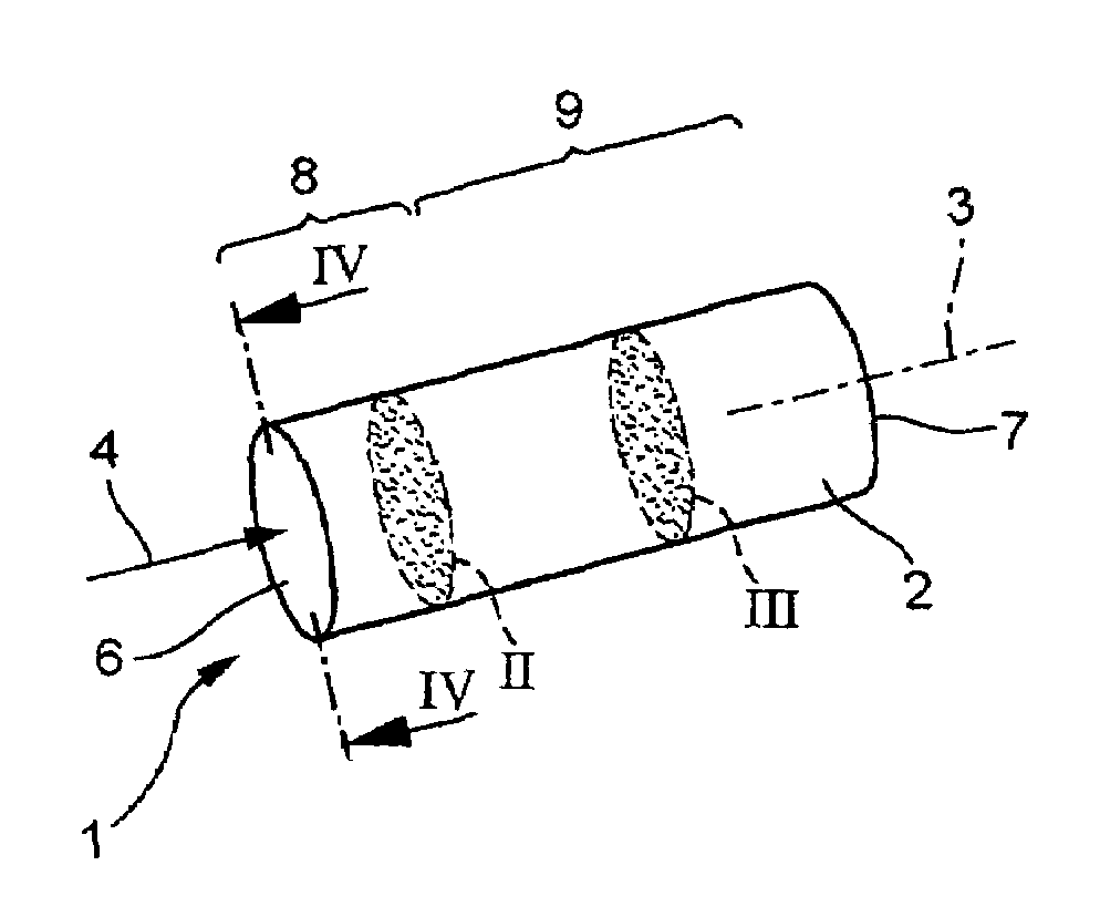
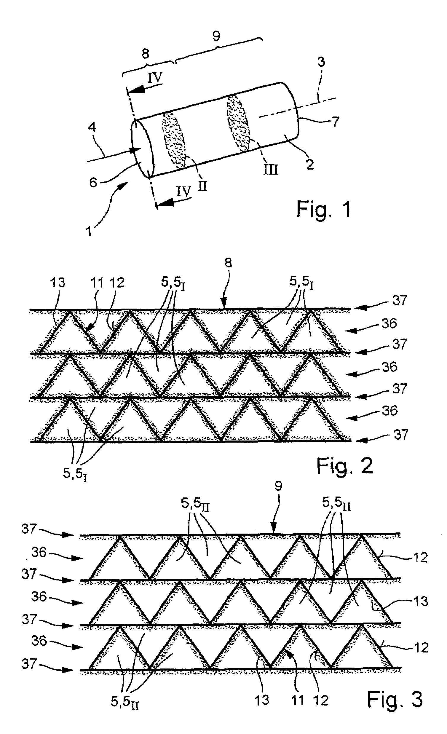
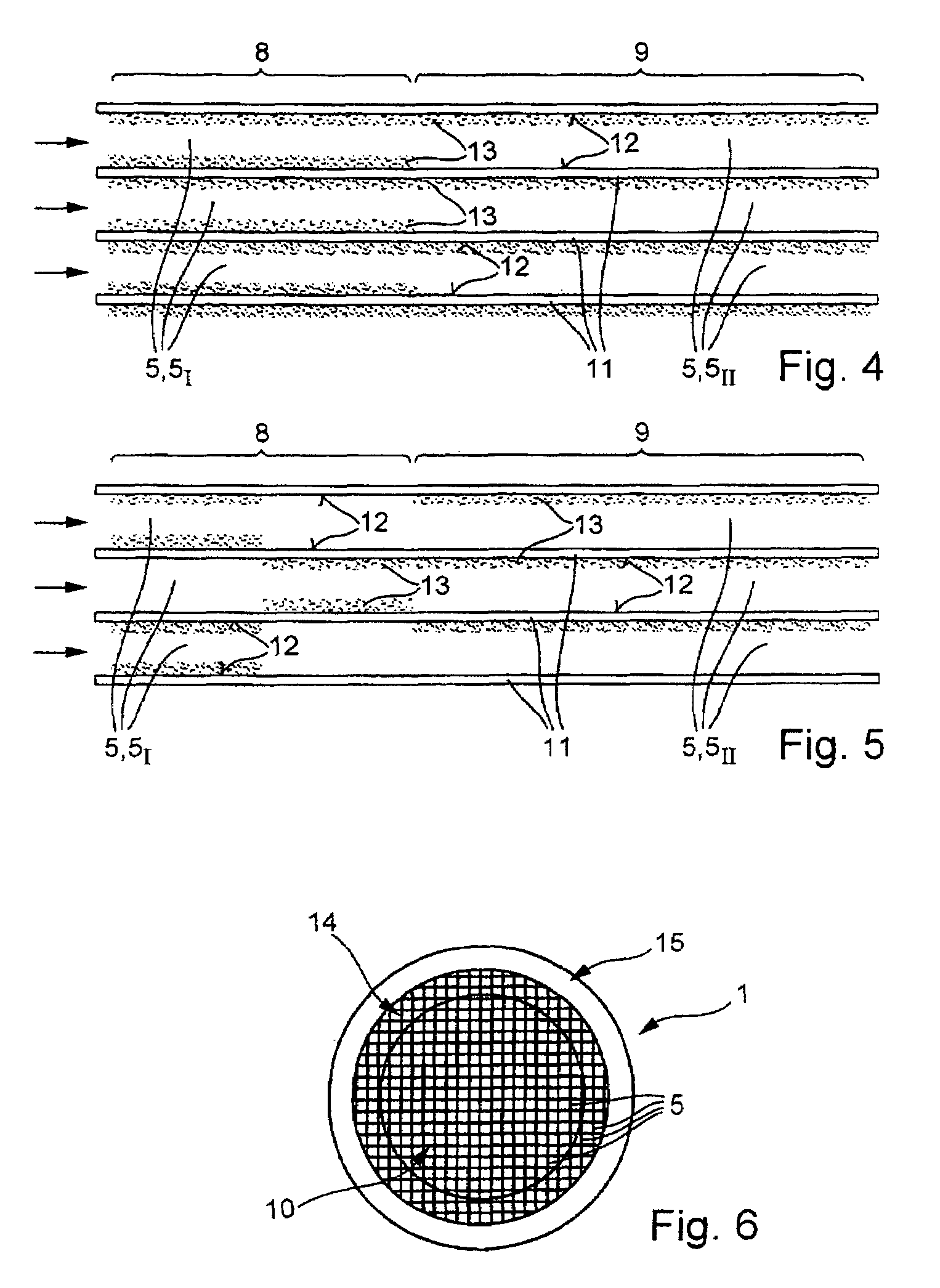
[0029]In accordance with FIG. 1, a catalytic reactor 1 according to the invention comprises a reactor body 2, which in this case is cylindrical, in particular circular-cylindrical, in form. In principle, other geometries are also possible. The reactor 1 has a longitudinal axis 3, which is oriented parallel to a flow symbolized by an arrow 4. The reactor 1 includes a multiplicity of parallel passages 5 (cf. FIGS. 2 to 6), which run parallel to the longitudinal axis 3 and through which the gas flow 4 can flow. Furthermore, the reactor 1 has an inlet side 6, onto which the gas flow 4 flows and through which the gas flow 4 enters the reactor 1 or its passages 5. The gas flow 4 emerges again from the passages 5 or from the reactor 1 at an outlet side 7 which is remote from the inlet side 6. The passages 5 extend from the inlet side 6 to the outlet side 7.

[0030]According to the invention, the reactor 1 is divided in its longitudinal direction 3 into two longitudinal parts, namely an upstr...


PUM

PropertyMeasurementUnit
inlet temperatureaaaaaaaaaa
inlet temperature TEaaaaaaaaaa

Abstract

A catalytic reactor for generating a hydrogen-containing synthesis gas from a rich fuel/oxidizing agent mix. The reactor (1) includes a multiplicity of parallel passages which extend from an inlet side (6) to an outlet side (7). To achieve a compact overall form of the reactor (1), at least in a core region of a cross section through the reactor (1) all the passages are of a catalytically active nature. In a first longitudinal part (8) of the reactor (1), which includes the inlet side (6), the catalytically active first passages have a larger proportion of the surface area provided with a catalytically active coating than the catalytically active second passages in a second longitudinal part (9) of the reactor (1), which includes the outlet side (7) and adjoins the first longitudinal part (8).

Description

[0001]This application claims priority under 35 U.S.C. § 119 to German Application No. 103 29 162.8, filed 27 Jun. 2003, the entirety of which is incorporated by reference herein.BACKGROUND OF THE INVENTION[0002]1. Field of the Invention[0003]The present invention relates to a catalytic reactor for generating a hydrogen-containing synthesis gas from a rich fuel / oxidizing agent mix. Moreover, the invention relates to an operating method for a reactor of this type and to a burner arrangement configured with a reactor of this type.[0004]2. Brief Description of the Related Art[0005]In the case of a burner arrangement, in particular for a gas turbine of a power plant, as is known, for example, from EP 1 265 029 A2, there is always a need to stabilize a flame front which forms in a combustion chamber when the burner arrangement is operating, in order on the one hand to achieve a combustion operation with minimum possible emissions of pollutants and in order on the other hand to prevent th...

Claims


Application Information

Patent Timeline
Patent Type & Authority Patents(United States)
IPC IPC(8): B01J35/02H01M2/00F23C13/00F23R3/40
CPCB01J19/2485C01B3/386F23R3/40F23C13/00C01B2203/0261C01B2203/141F23C2900/03002F23C2900/9901C01B2203/142Y02P20/52
Inventor CARRONI, RICHARDGRIFFIN, TIMOTHYWOLF, MARKUS
Owner ANSALDO ENERGIA SWITZERLAND AG
Why Eureka
Try Eureka