
Wideband variable gain amplifier with clipping function

a wideband variable gain amplifier and function technology, applied in amplifiers with tubes, applications, ultrasonic/sonic/infrasonic diagnostics, etc., can solve the problem of not getting accurate ultrasound image signals

Active Publication Date: 2010-02-02
SAMSUNG MEDISON +1
View PDF6 Cites 3 Cited by
  • Summary
  • Abstract
  • Description
  • Claims
  • Application Information

AI Technical Summary

Benefits of technology

The present invention relates to a wide-band variable gain amplifier for an ultrasound diagnostic system. The technical effect of the invention is to provide a wide-band amplifier that can compensate for attenuation of ultrasound signals during propagation in the target object by adjusting the gain of the pre-amplified analog receive signals within a limited amplitude range. The amplifier can also clip the analog receive signals to be within a predetermined voltage range to prevent malfunctions of the analog-to-digital converter and to obtain an accurate ultrasound image. The invention provides a solution for improving the quality and accuracy of ultrasound diagnostic systems.

Problems solved by technology

If the analog receive signals are amplified beyond an allowable amplitude range as an ADC input or a recovery time is increased due to overload, the ADC may malfunction so that an accurate ultrasound image signal may be not obtained.

Method used


Image

  • Wideband variable gain amplifier with clipping function
  • Wideband variable gain amplifier with clipping function
  • Wideband variable gain amplifier with clipping function

Examples


Embodiment Construction

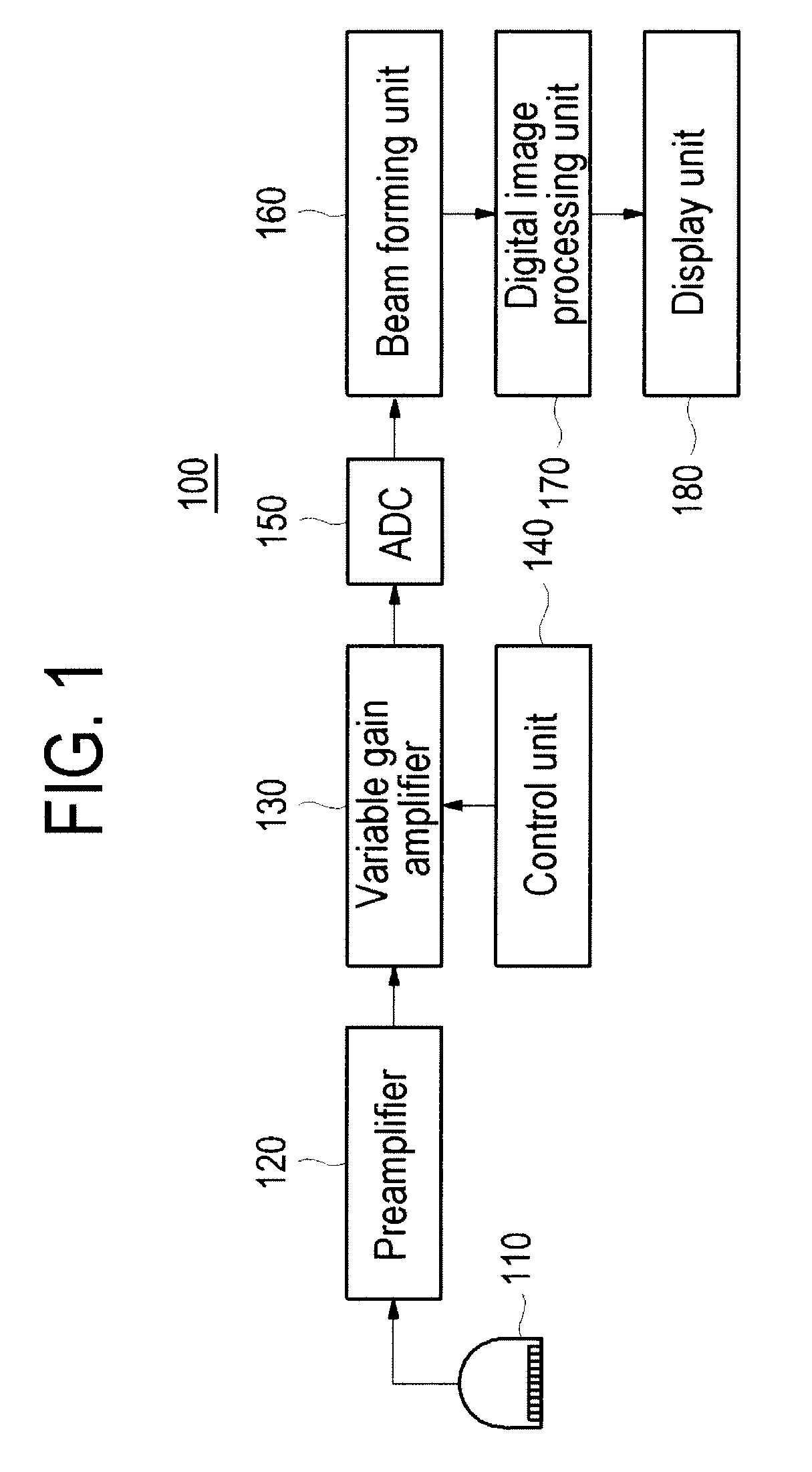
[0016]FIG. 1 is a block diagram showing an ultrasound diagnostic system constructed in accordance with the present invention. As shown in FIG. 1, the ultrasound diagnostic system 100 includes a probe 110, a preamplifier 120, a variable gain amplifier 130, a control unit 140, an analog-to-digital converter (ADC) 150, a beam forming unit 160, a digital image processing unit 170 and a display unit 180.

[0017]The probe 110 may include at least one transducer element. An array transducer may be included in the probe 110. The probe 110 may be operable to generate ultrasound signals to be transmitted to a target object in response to electrical transmit pulses. The probe 110 may be further operable to convert echo signals reflected from the target object into electrical analog receive signals. The preamplifier 120 may be operable to amplify the analog receive signals, the amplitudes of which are low, so as to be processed in the ultrasound diagnostic system.

[0018]The variable gain amplifier...


PUM


Abstract

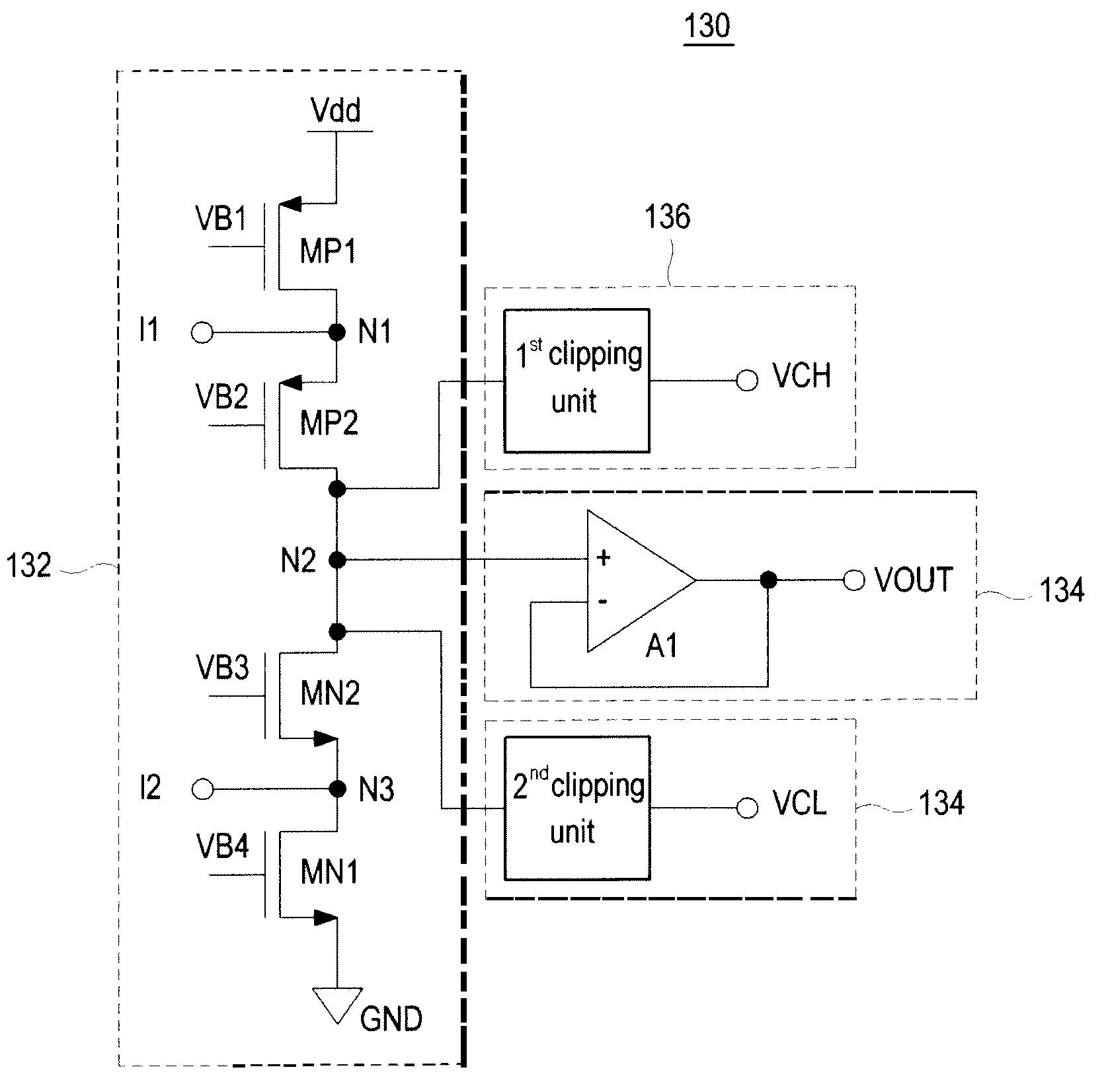
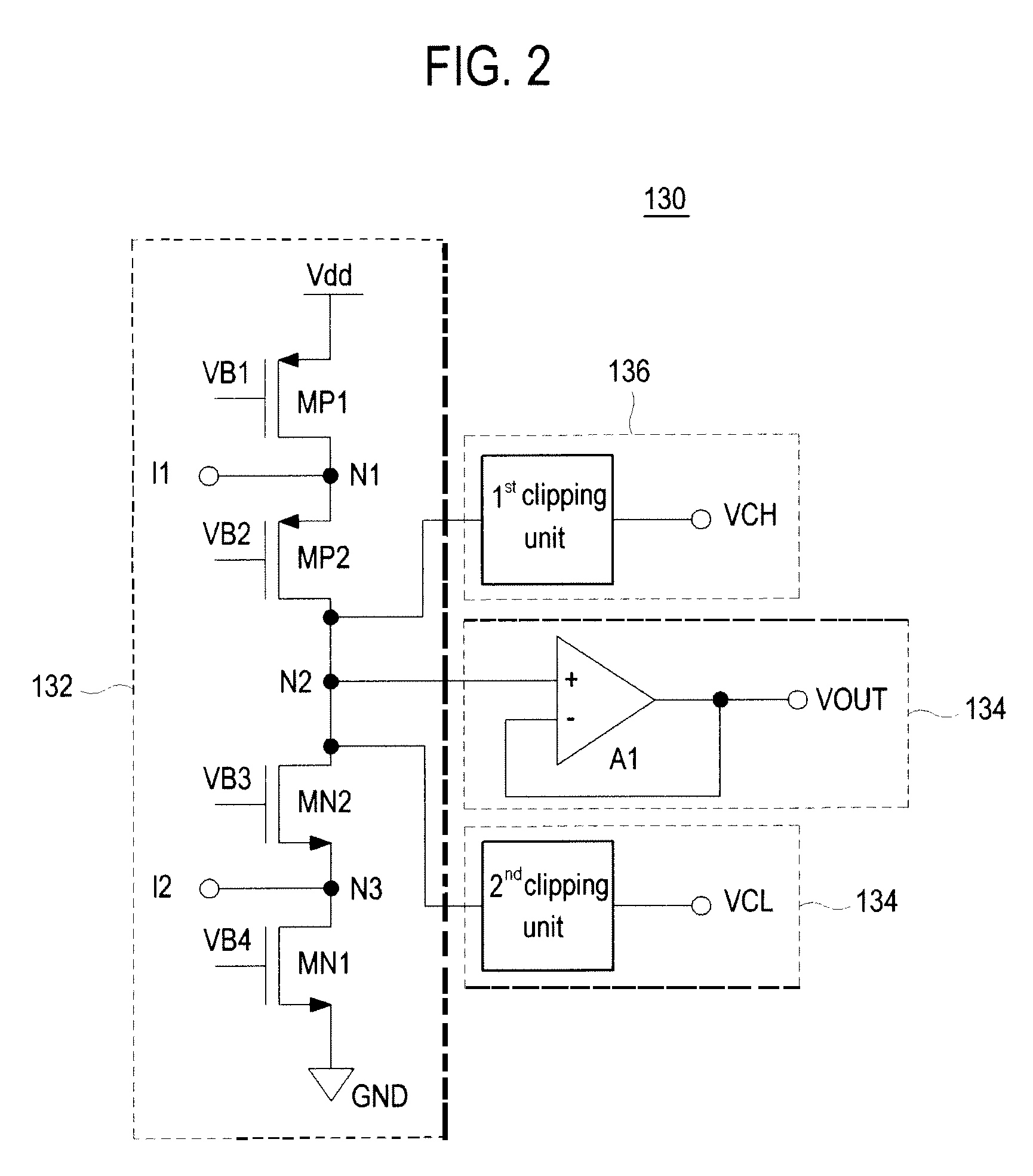
The present invention relates to a variable gain amplifier. The variable gain amplifier includes an input unit including first and second input nodes and an output node, the input unit being configured to receive first and second input signals. The variable gain amplifier further includes a first clipping unit operable to clip a voltage level at the output node to be equal to or lower than a level of a first reference voltage and a second clipping unit operable to clip a voltage level at the output node to be equal to or greater than a level of a second reference voltage, wherein the second reference voltage is lower than the first reference voltage. A predetermined level of a voltage is outputted through an output unit included in the variable gain amplifier based on the clipped voltage level.

Description

[0001]The present application claims priority from Korean Patent Application No. 10-2007-0064885 filed on Jun. 29, 2007, the entire subject matter of which is incorporated herein by reference.BACKGROUND OF THE INVENTION[0002]1. Technical Field[0003]The present invention generally relates to a variable gain amplifier, and more particularly to a wide-band variable gain amplifier with a clipping function.[0004]2. Background Art[0005]The ultrasound system has become an important and popular diagnostic tool due to its non-invasive and non-destructive nature. Modern high-performance ultrasound imaging diagnostic systems and techniques are commonly used to produce two- or three-dimensional images of internal features of patients.[0006]An ultrasound system generally uses a probe containing an array of piezoelectric elements to transmit and receive ultrasound signals. The ultrasound system forms an image of human internal tissues by electrically exciting transducer elements to generate ultra...

Claims


Application Information

Patent Timeline
Patent Type & Authority Patents(United States)
IPC IPC(8): H03G3/00
CPCH03G11/002A61B8/00
Inventor KIM, CHANG SUNJEON, KI
Owner SAMSUNG MEDISON
Learn More