Low energy magnetic actuator

a low-energy magnetic actuator and low-energy technology, applied in the direction of magnetic field change switches, electrical devices, electromagnets, etc., can solve the problems of requiring a relatively large amount of electrical energy to operate, the use of electromagnets to effectuate magnetic fields suffers, etc., to achieve low-energy actuation, effectively block the magnetic field, and reduce the effect of emitted magnetic field

Inactive Publication Date: 2010-02-02
STEORN
View PDF15 Cites 1 Cited by
  • Summary
  • Abstract
  • Description
  • Claims
  • Application Information

AI Technical Summary

Benefits of technology

[0007]A low energy magnet actuator allows magnetic fields to be turned on and off using a small amount of energy. The magnetic actuator according to the invention generally includes a base suitable for the support of a plurality of magnets. An actuatable shield is positioned in relation to the plurality of magnets so that it effectively blocks the magnetic field when it is positioned over at least one of the magnets. The magnetic fields of the plurality of magnets interact in a manner that allows low energy actuation of the shield.
[0008]In one illustrative embodiment of an actuator according to the invention, the base supports a first magnet mounted to the base in a first position. A second magnet is supported by the base in a second position relative to the first magnet. A shield is positioned relative to the first and second magnets in a configuration that enables the movement of the shield between two known positions. In this illustrative embodiment, each magnet is of similar field strength and the field that radiates from the ends are of the same polarity. The shield is of a thickness that effectively blocks the emitted magnetic field when positioned over one or the other of the magnets. The magnetic fields of the two magnets interact in a manner that allows for the low-energy movement of the shield. The exposed magnetic field may be used to perform work (e.g. interact with other magnetic fields to move an object).
[0009]Advantages of the actuator according to the invention include low energy actuation of the shield in a manner that yields motion or actuation that is highly efficient. The highly efficient actuation of the shield results in movement that can perform work in a highly efficient manner.

Problems solved by technology

The use of electromagnets to effectuate magnetic fields suffers from one major drawback—the electromagnet requires a relatively large amount of electrical energy to operate.

Method used


Image

  • Low energy magnetic actuator
  • Low energy magnetic actuator
  • Low energy magnetic actuator

Examples


Embodiment Construction

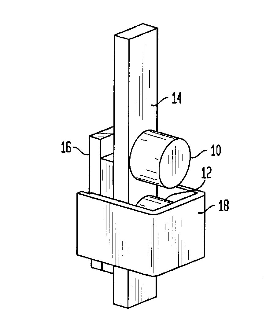
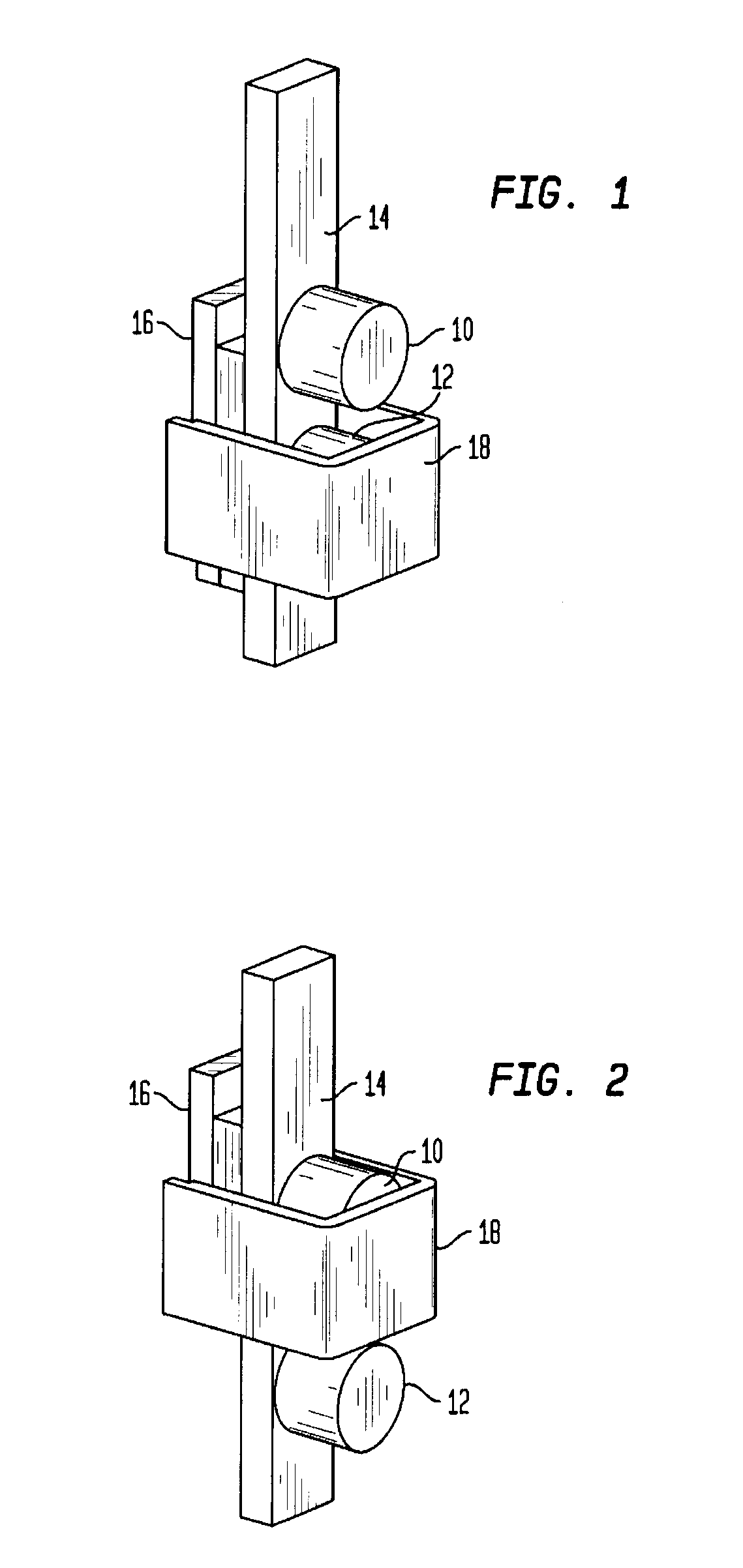
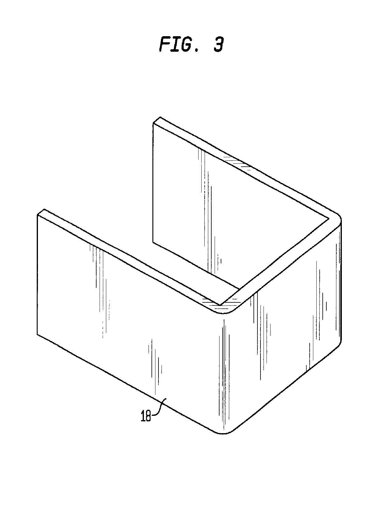
[0017]The present invention is an actuator configuration that involves a plurality of magnetic fields working in conjunction to effect motion in a highly efficient manner.

[0018]Referring now to FIGS. 1-3, a first illustrative embodiment of an actuator according to the invention comprises a first magnet 10 and a second magnet 12 disposed on a base 14. In this embodiment the first and second magnets are fixed to the base along a longitudinal axis of the base such that the magnetic axis of each magnet is perpendicular to the longitudinal axis of the base and the magnetic axis of the first and second magnets are linearly displaced from each other along the longitudinal axis of the base. The base is disposed proximate to a linear bearing. The base 14 and linear bearing are configured to move relative to each other along the longitudinal axis of the base in this embodiment. A shield 18 is disposed in a manner to move relative to the first magnet 10 and the second magnet 12 such that shiel...


PUM


Abstract

A low energy magnet actuator allows magnetic fields to be turned on and off using a small amount of energy. The magnetic actuator according to the invention generally includes a base suitable for the support of a plurality of magnets. An actuatable shield is positioned in relation to the plurality of magnets so that it effectively blocks the magnetic field when it is positioned over at least one of the magnets. The magnetic fields of the plurality of magnets interact in a manner that allows low energy actuation of the shield.

Description

RELATED CASE INFORMATION[0001]This application claims benefit of U.S. Provisional Application No. 60 / 613,565, filed Sep. 27, 2004, which is incorporated by reference herein in its entirety.FIELD OF THE INVENTION[0002]The present invention relates to a magnetic actuating apparatus.BACKGROUND OF THE INVENTION[0003]Electromagnets are commonly used where there is a requirement for a magnetic field to be actuated (turned on / off).[0004]An electromagnet achieves this effect by providing (generating) a magnetic field while electrical current is applied to it. To turn off the field the current is no longer applied to the electromagnet.[0005]The use of electromagnets to effectuate magnetic fields suffers from one major drawback—the electromagnet requires a relatively large amount of electrical energy to operate.[0006]Many techniques are being used to reduce the amount of external energy that an electromagnet requires. Primarily these techniques relate to the efficiency of the electromagnet an...

Claims


Application Information

Patent Timeline
Patent Type & Authority Patents(United States)
IPC IPC(8): H01H9/00
CPCH01F7/0205H01F7/0252H01H36/008E05B2047/0007
Inventor MCCARTHY, SHAUN DAVIDDALY, MICHAEL ANDREWSIMPSON, ALAN
Owner STEORN
Why Eureka
Try Eureka