System and method for specifying batch execution ordering of requests in a storage system cluster

a storage system and batch execution technology, applied in the field of network protocols, can solve the problems of not being able to execute requests out-of-order or concurrently within the channel, and not being able to enforce the ordering of requests in different channels with respect to each other,

Active Publication Date: 2010-02-02
NETWORK APPLIANCE INC
View PDF34 Cites 61 Cited by
  • Summary
  • Abstract
  • Description
  • Claims
  • Application Information

AI Technical Summary

Benefits of technology

[0017]Advantageously, batch execution ordering allows multiple requests to be executed concurrently or out of sequence, while explicitly requiring ordering among subsets of requests. That is, the use of batch numbers within a channel allows imposition of an ordering constraint on requests in the channel, as well as issuance of multiple unordered requests in the channel. Moreover, layering of a batch number on a request id allows immediate and certain detection of a boundary between batches with no danger of error. In other words, the batch number enables a responder to determine whether a request can be immediately executed or must be stalled, and this determination can always be made optimally based on other requests received at that point.

Problems solved by technology

Laggard response messages (responses) or long-running requests may force the institution of session layer flow control to limit the flow of requests between the processes, thereby adversely impacting the session.
However, if the sequence number is also used to specify an order of execution of requests, then no requests can be executed out-of-order or concurrently within the channel.
Requests on different channels can be executed concurrently or out-of-order respect to each other, but there is no way to enforce an ordering of the requests in different channels with respect to each other.

Method used


Image

  • System and method for specifying batch execution ordering of requests in a storage system cluster
  • System and method for specifying batch execution ordering of requests in a storage system cluster
  • System and method for specifying batch execution ordering of requests in a storage system cluster

Examples


Embodiment Construction

[0031]A. Cluster Environment

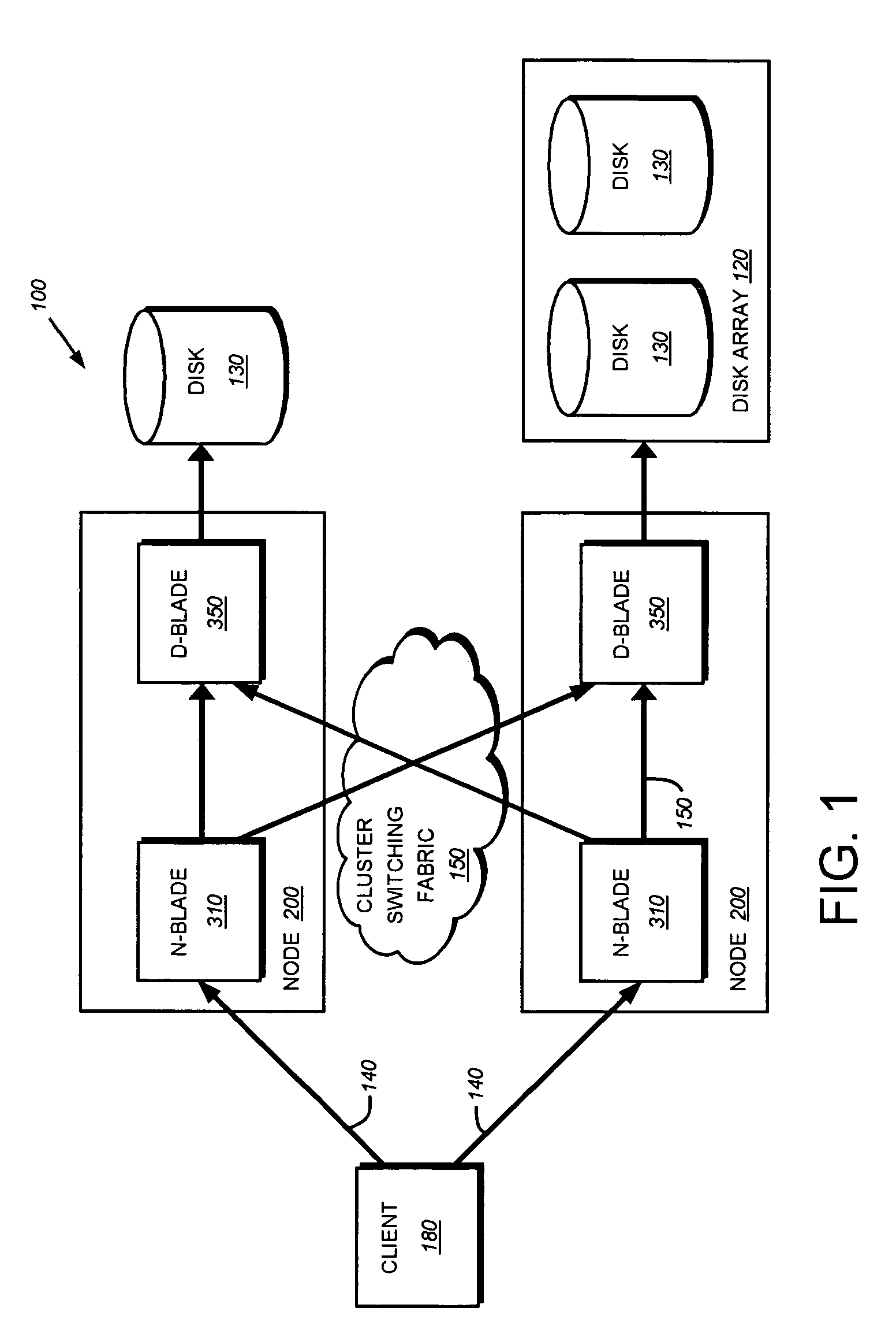
[0032]FIG. 1 is a schematic block diagram of a plurality of nodes 200 interconnected as a cluster 100 and configured to provide storage service relating to the organization of information on storage devices. The nodes 200 comprise various functional components that cooperate to provide a distributed storage system architecture of the cluster 100. To that end, each node 200 is generally organized as a network element (N-blade 310) and a disk element (D-blade 350). The N-blade 310 includes functionality that enables the node 200 to connect to clients 180 over a computer network 140, while each D-blade 350 connects to one or more storage devices, such as disks 130 of a disk array 120. The nodes 200 are interconnected by a cluster switching fabric 150 which, in the illustrative embodiment, may be embodied as a Gigabit Ethernet switch. An exemplary distributed file system architecture is generally described in U.S. Patent Application Publication No. US 2002 / 01...


PUM


Abstract

A system and method specifies batch execution ordering of requests in a cluster of storage systems or nodes. Each node is generally organized as a network element and a disk element. One or more sessions are established between the elements in the cluster. Each session comprises a plurality of channels disposed over connections, wherein each channel enables multiple requests to be sent over a connection. Each request is identified by a unique identifier (“request id”) that is generally defined as the combination of a channel number and a sequence number. The request id is extended to include a batch number that provides an execution ordering directive within a channel. All requests with the same batch number in a channel can be executed in arbitrary order or concurrently. Ordering is imposed only when the batch number changes, e.g., increases. Although more than one request in a channel can have the same batch number, all requests with the same batch number are executed before any request with a higher batch number.

Description

CROSS-REFERENCE TO RELATED APPLICATION[0001]The present application is related to U.S. patent application Ser. No. 11 / 118,466 entitled, SYSTEM AND METHOD FOR MULTIPLEXING CHANNELS OVER MULTIPLE CONNECTIONS IN A STORAGE SYSTEM CLUSTER, which application is hereby incorporated by reference.FIELD OF THE INVENTION[0002]The present invention is directed to network protocols and, in particular, to ordering of message operation execution in accordance with a network protocol executing on a storage system cluster.BACKGROUND OF THE INVENTION[0003]A storage system typically comprises one or more storage devices into which information may be entered, and from which information may be obtained, as desired. The storage system includes a storage operating system that functionally organizes the system by, inter alia, invoking storage operations in support of a storage service implemented by the system. The storage system may be implemented in accordance with a variety of storage architectures incl...

Claims


Application Information

Patent Timeline
Patent Type & Authority Patents(United States)
IPC IPC(8): G06F7/00G06F17/30
CPCG06F3/0614G06F3/0659G06F3/067G06F15/17331H04L67/2833H04L67/1097H04L67/141H04L67/566
Inventor CORBETT, PETER F.
Owner NETWORK APPLIANCE INC
Why Eureka
Try Eureka