Inkjet printhead with multiple heater elements and cross bracing
What is AI technical title?
AI technical title is built by Patsnap AI team. It summarizes the technical point description of the patent document.
a technology of cross bracing and heater elements, applied in the field of inkjet printheads, can solve the problems of altering the shape of pressure pulses generated, unintentional ink boiling becomes an issue,
Inactive Publication Date: 2010-02-16
MEMJET TECH LTD +1
View PDF10 Cites 28 Cited by
Summary
Abstract
Description
Claims
Application Information
AI Technical Summary
This helps you quickly interpret patents by identifying the three key elements:
Problems solved by technology
Method used
Benefits of technology
Benefits of technology
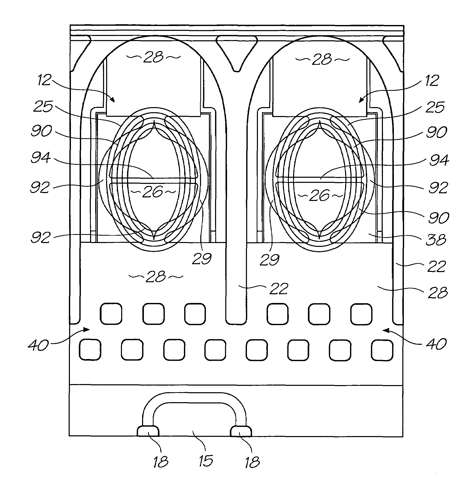
The present invention provides an inkjet printhead with improved control of ink droplets and better shaping of pressure pulse. The printhead has an array of ink chambers with heater elements for generating vapour bubbles to eject ink through the nozzle. The heater elements are suspended within the ink chamber to isolate them from the substrate and prevent excess heating. The cross bracing structure maintains the spacing between the heater elements and preserves the shape of the pressure pulse. The heater elements nucleate bubbles simultaneously with every activation of the actuator, and the ink chambers have a plurality of nozzles aligned with the actuator. The ink chambers have elongate shapes with the nozzle long dimension aligned with the actuator. The inkjet printhead also includes a drive circuitry for each heater element and an ink conduit for supplying ink to the chambers. The ink chambers have elongate shapes and the nozzles are arranged in rows with a greater nozzle pitch per inch.
Problems solved by technology
The heat generated by several heater elements would normally heat the wafer substrate so much that unintentional ink boiling would become an issue.
This changes their relative positioning and therefore alters the shape of the pressure pulse they generate.
Method used
Image
Click on the blue label to locate the original text in one second.
Reading with bidirectional positioning of images and text.
Examples
Embodiment Construction
[0277]In the description than follows, corresponding reference numerals relate to corresponding parts. For convenience, the features indicated by each reference numeral are listed below.
[0278]
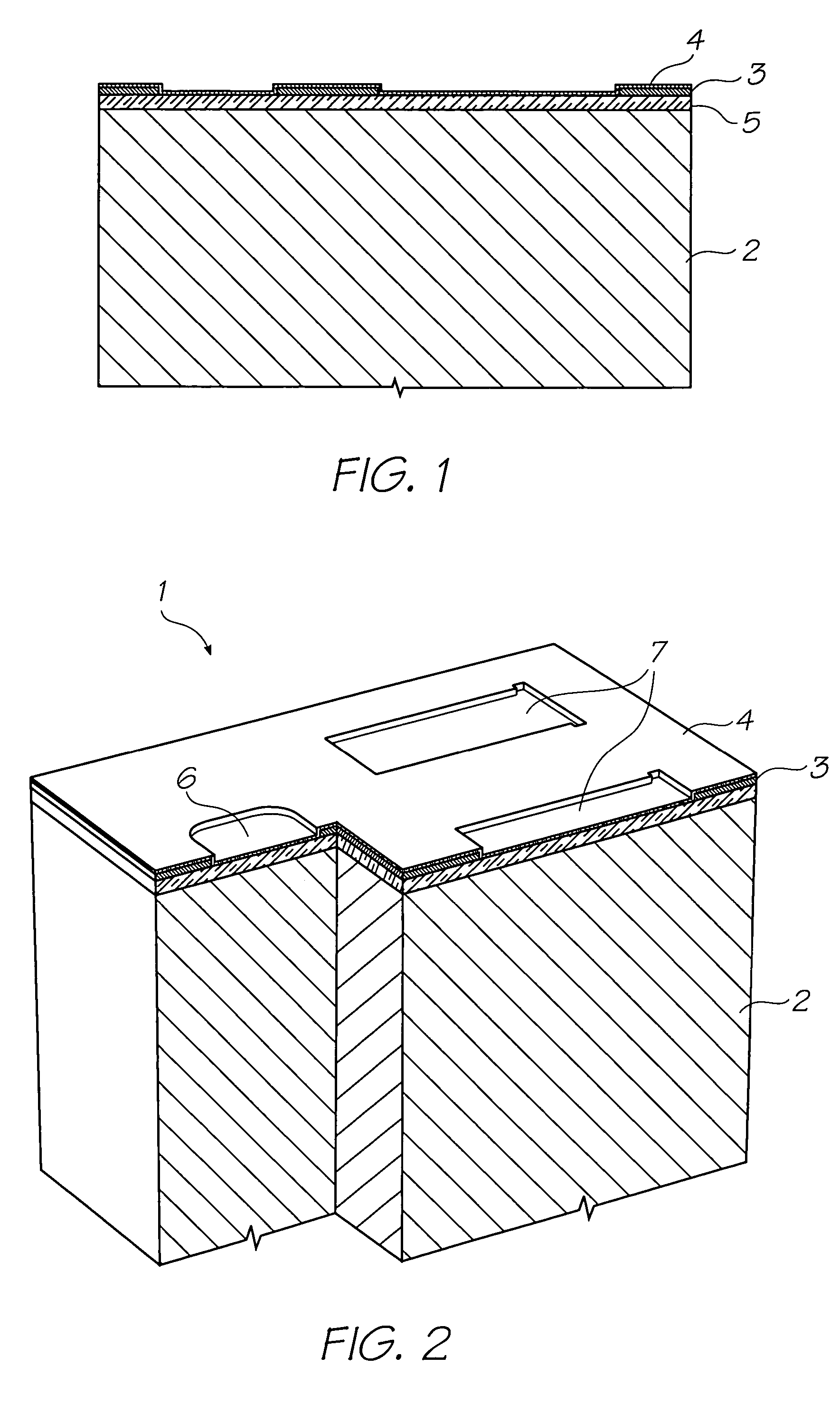
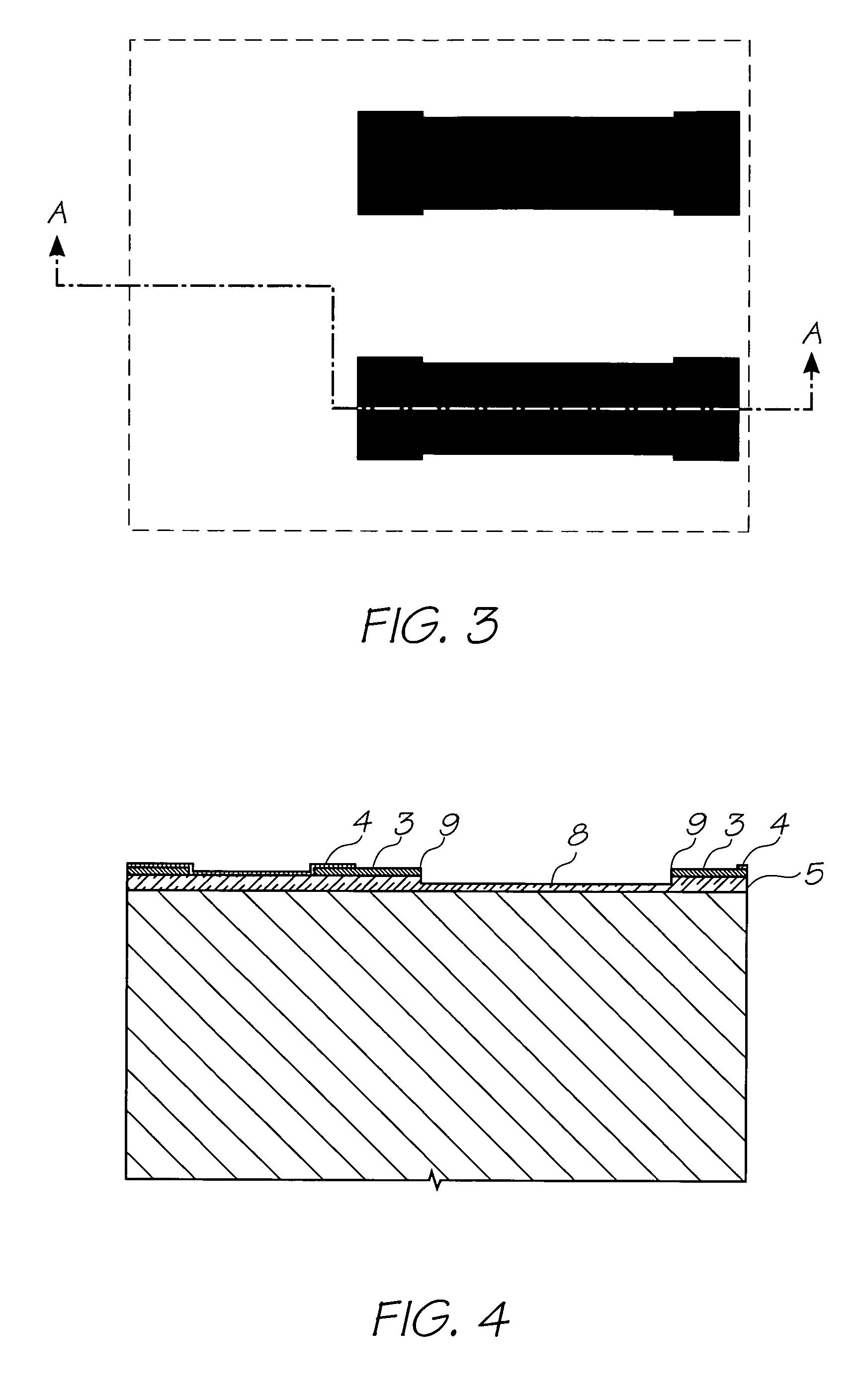
1.Nozzle Unit Cell2.SiliconWafer3.Topmost AluminiumMetal Layer in the CMOSmetallayers4.Passivation Layer5.CVD Oxide Layer6.Ink Inlet Opening in Topmost AluminiumMetal Layer 3.7.Pit Opening in Topmost AluminiumMetal Layer 3.8.Pit9.Electrodes10.SAC1 Photoresist Layer11.Heater Material (TiAlN)12.Thermal Actuator13.Photoresist Layer14.Ink Inlet Opening Etched Through Photo Resist Layer15.Ink Inlet Passage16.SAC2 Photoresist Layer17.Chamber Side Wall Openings18.Front Channel Priming Feature19.Barrier Formation at Ink Inlet20.Chamber Roof Layer21.Roof22.Sidewalls23.Ink Conduit24.Nozzle Chambers25.Elliptical Nozzle Rim25(a) Inner Lip25(b) Outer Lip26.Nozzle Aperture27.Ink Supply Channel28.Contacts29.Heater Element.30.Bubble cage32.bubble retention structure34.ink permeable structure36.bleed hole...
PUM
Abstract
An inkjet printhead having: an array of ink chambers, each having a nozzle and a plurality of heater elements for generating vapour bubbles to eject ink through the nozzle, the heater elements being suspended for immersion in the ink; and, a cross bracing structure for maintaining the spacing between the heater elements.
Description
CO-PENDING APPLICATIONS[0001]The following applications have been filed by the Applicant simultaneously with the present application:[0002]11 / 246,67611 / 246,67711 / 246,67811 / 246,67911 / 246,68011 / 246,68111 / 246,71411 / 246,71311 / 246,68911 / 246,67111 / 246,67011 / 246,66911 / 246,70411 / 246,71011 / 246,68811 / 246,71611 / 246,7157,367,64811 / 246,70611 / 246,70511 / 246,70811 / 246,69311 / 246,69211 / 246,69611 / 246,69511 / 246,69411 / 246,68711 / 246,7187,322,68111 / 246,68611 / 246,70311 / 246,69111 / 246,71111 / 246,69011 / 246,71211 / 246,71711 / 246,70911 / 246,70011 / 246,70111 / 246,70211 / 246,66811 / 246,69711 / 246,69811 / 246,69911 / 246,67511 / 246,6677,303,93011 / 246,67211 / 246,67311 / 246,68311 / 246,682[0003]The disclosures of these co-pending applications are incorporated herein by reference.CROSS REFERENCES TO RELATED APPLICATIONS[0004]Various methods, systems and apparatus relating to the present invention are disclosed in the following U.S. Patents / Patent Applications filed by the applicant or assignee of the present invention:[0005]6,750,9016...
Claims
Application Information
Patent Timeline
Application Date:The date an application was filed.
Publication Date:The date a patent or application was officially published.
First Publication Date:The earliest publication date of a patent with the same application number.
Issue Date:Publication date of the patent grant document.
PCT Entry Date:The Entry date of PCT National Phase.
Estimated Expiry Date:The statutory expiry date of a patent right according to the Patent Law, and it is the longest term of protection that the patent right can achieve without the termination of the patent right due to other reasons(Term extension factor has been taken into account ).
Invalid Date:Actual expiry date is based on effective date or publication date of legal transaction data of invalid patent.

