Method for ejecting liquid material, method for manufacturing organic electroluminescense device, and method for manufacturing color filter

a technology of organic electroluminescence and liquid material, which is applied in the direction of manufacturing tools, liquid/solution decomposition chemical coating, superimposed coating process, etc., can solve the problems of inaccurate control of droplet landing position and no specific method for accurately controlling landing position errors in the nozzle-row direction (y direction), and achieves high yield and suppresses failures.

Active Publication Date: 2010-02-16
KATEEVA
View PDF5 Cites 1 Cited by
  • Summary
  • Abstract
  • Description
  • Claims
  • Application Information

AI Technical Summary

Benefits of technology

[0010]In this method, the ejection is performed in such a manner that, for each of the nozzle groups having different landing position accuracies of droplets, the relative positions of the substrate and the plurality of nozzles in the sub-scanning direction are corrected, and the main scanning is performed by using at least one selected nozzle. Therefore, even if the target regions are arranged with a high definition, droplets can be provided to the target regions with a high landing position accuracy. Accordingly, even with nozzles that do not meet the required level of landing position accuracy, a substantially high landing position accuracy can be realized.
[0018]By this method, droplets can be kept from at least landing outside desired target regions. Accordingly, in the case where liquid materials of different kinds are ejected toward different target regions, the liquid materials can be prevented from being mixed together.
[0022]By this method, even if droplets land on the bank, the droplets can be kept from remaining outside the target regions. Accordingly, a required volume of a liquid material in a form of droplets can be more assuredly provided to each target region.
[0024]In this method, by measuring the landing positions of the droplets that have landed along the virtual straight line on the ejection target, accurate information on the landing position of each nozzle can be acquired.
[0028]By this method, even if the light-emitting-layer regions are arranged with a high definition on the substrate, a required volume of a liquid material in a form of droplets can be made to land on each light-emitting-layer region. This suppresses the occurrence of landing failure, whereby a high-definition organic EL device can be manufactured at a high yield.
[0030]This method suppresses the occurrence of failure, such as color mixing due to landing failure, whereby a high-definition color filter can be manufactured at a high yield.

Problems solved by technology

In such a head correcting method, however, it is still difficult to accurately control the droplet landing position.
However, no specific method for accurately controlling landing position errors in the nozzle-row direction (Y direction) has been described in JP-A-2004-58282.

Method used


Image

  • Method for ejecting liquid material, method for manufacturing organic electroluminescense device, and method for manufacturing color filter
  • Method for ejecting liquid material, method for manufacturing organic electroluminescense device, and method for manufacturing color filter
  • Method for ejecting liquid material, method for manufacturing organic electroluminescense device, and method for manufacturing color filter

Examples


first embodiment

Liquid Ejecting Apparatus

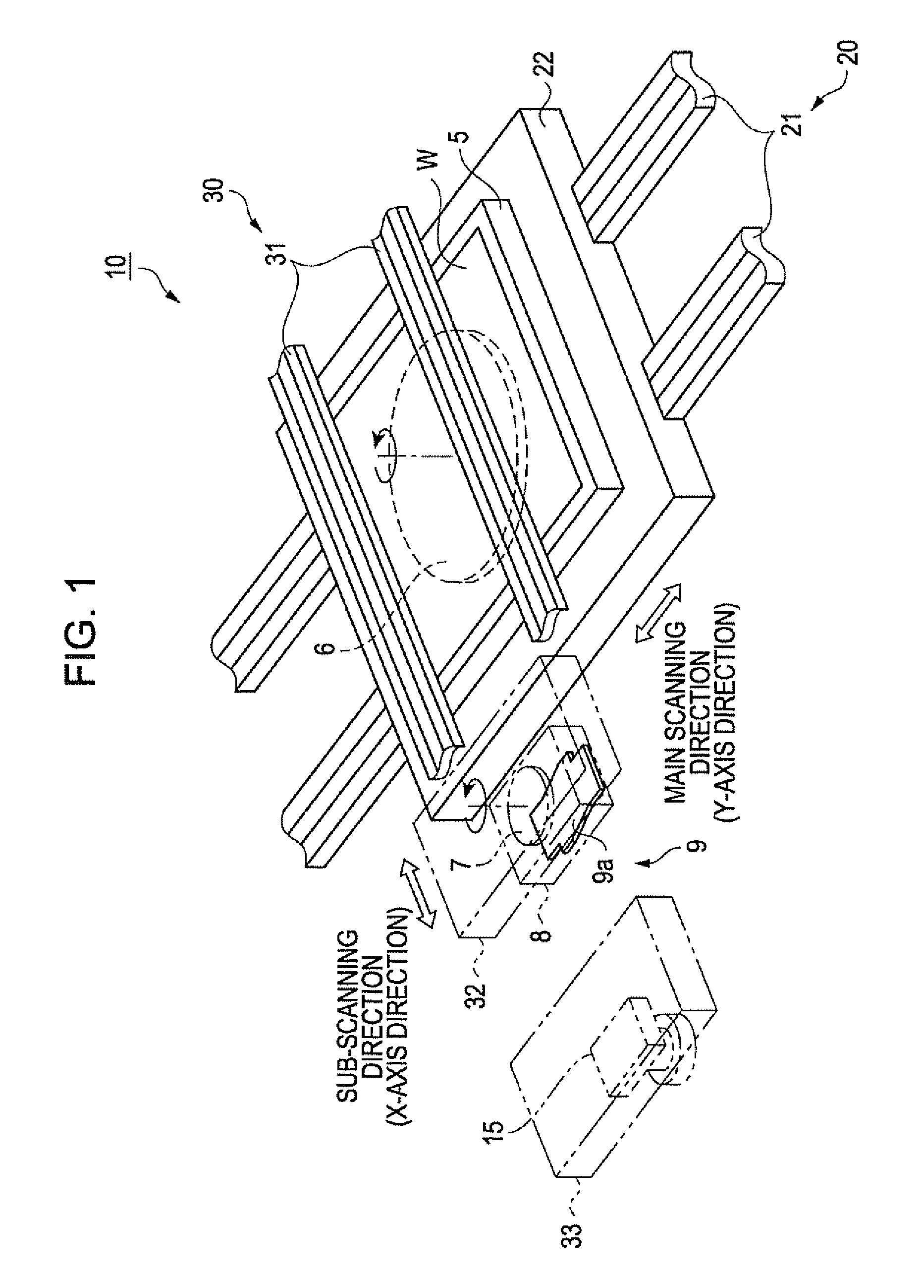
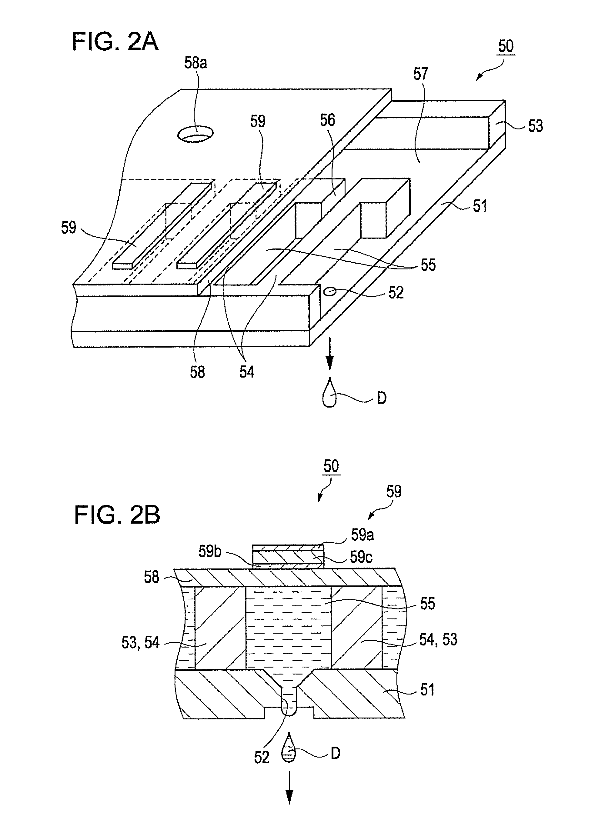
[0061]Referring to FIGS. 1 to 5, a liquid ejecting apparatus including a liquid ejecting head capable of ejecting a liquid material containing a high-performance material in a form of droplets will be described. FIG. 1 is a schematic perspective view of the liquid ejecting apparatus.

[0062]Referring to FIG. 1, a liquid ejecting apparatus 10 includes a workpiece moving mechanism 20 that moves a substrate W, a workpiece, in a main scanning direction (the Y-axis direction), and a head moving mechanism 30 that moves a head unit 9, on which liquid ejecting heads 50 (see FIG. 2) are mounted, in a sub-scanning direction (the X-axis direction).

[0063]The workpiece moving mechanism 20 includes a pair of guide rails 21, a movable base 22 that moves along the guide rails 21, and a set table 5 that is disposed on the movable base 22 with a θ table 6, which is a turnable mechanism, interposed therebetween. The substrate W is set on the set table 5. The movable base 22 move...

example 1

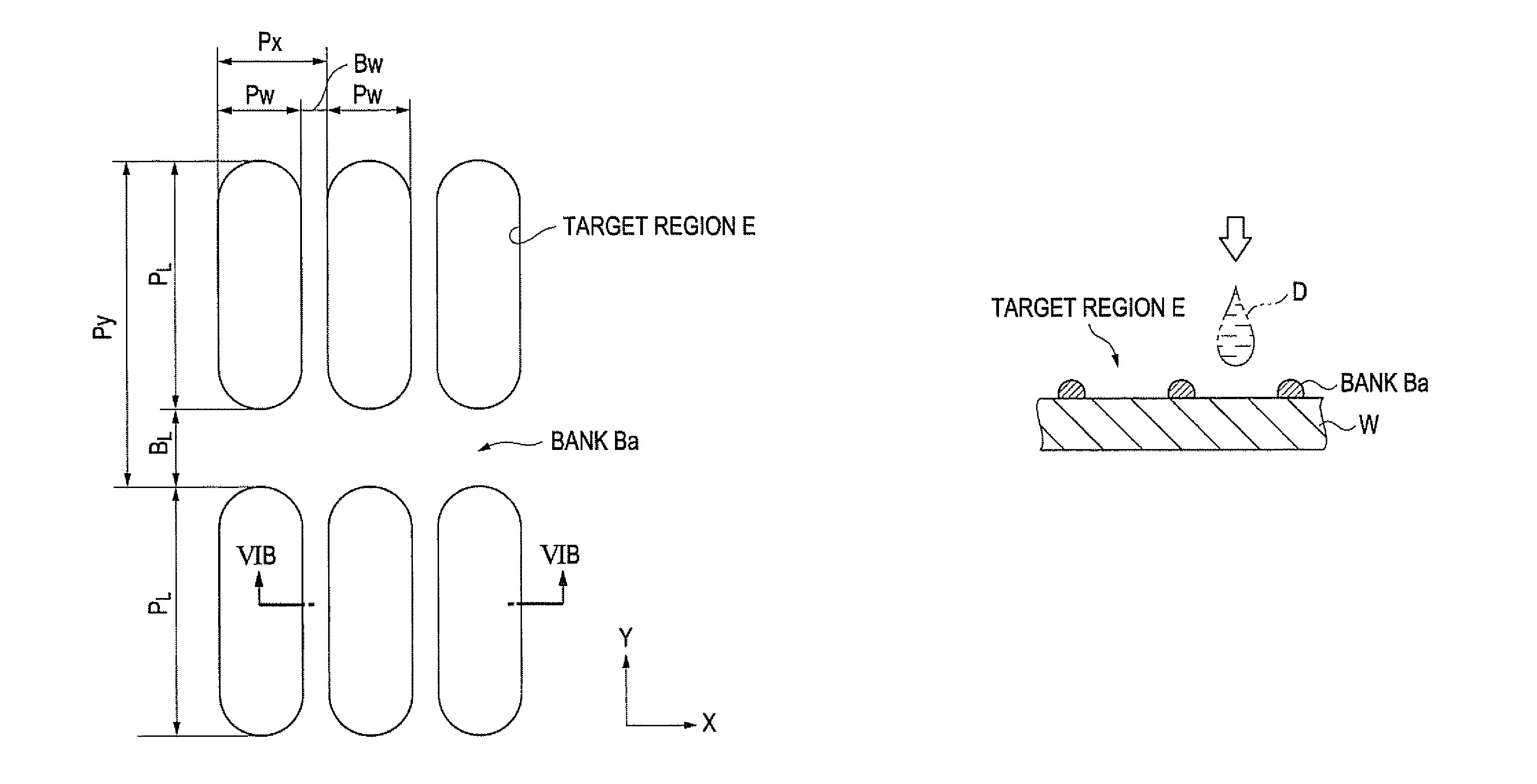
[0112]Referring to FIG. 11, in step S3, which is the arrangement-information generating step, arrangement information used for arranging four droplets D in each predetermined target region E as shown in FIGS. 12A and 12B is generated by the host computer 11. Among the target regions E arranged in a matrix with a density of 400 ppi, every two other target regions E in the X-axis direction are to be provided with a liquid material of the same kind. These target regions E are continuously aligned in the Y-axis direction. In this case, the liquid ejecting head 50 is angled in plan view when being positioned to face the substrate W, whereby the nozzle pitch P1 (about 140 μm) and the arrangement pitch (about 63 μm) of the target regions E to be provided with the liquid material of the same kind are matched. The direction in which the liquid ejecting head 50 is angled is arbitrary. Practically, the turnable mechanism 7 of the liquid ejecting apparatus 10 is driven to turn the head unit 9, ...

example 2

[0118]The relative arrangement between the nozzles 52 and the target regions E in the ejecting step is not limited to that described above. For example, referring to FIGS. 13A to 14B, a method for ejecting a liquid material according to Example 2 employs an arrangement in which the target regions E are oriented so as to extend in the X-axis direction, and a liquid material of the same kind is ejected in a form of droplets D toward some target regions E that are continuously aligned in the X-axis direction. Also in Example 2, four droplets D are provided for each of these target regions E.

[0119]First, referring to FIG. 13A, the liquid ejecting head 50 is turned with respect to the substrate W in such a manner that droplets D1 can each land near one of the X-axis ends of the target region E. The nozzle pitch P1 and the X-axis arrangement pitch (about 63 μm) of the target regions E are matched. Then, in accordance with arrangement information on the droplets D1 and correction informati...


PUM

PropertyMeasurementUnit
diameteraaaaaaaaaa
width Bwaaaaaaaaaa
width BLaaaaaaaaaa

Abstract

A method for ejecting a liquid material includes classifying the plurality of nozzles of a head into a plurality of nozzle groups having different landing position accuracies for droplets; and performing ejection includes main scanning for ejecting droplets of the liquid material through selected nozzles while generating relative movement in a main-scanning direction between the head and a target substrate, and sub-scanning for generating relative movement between the head and the target substrate in a sub-scanning direction orthogonal to the main-scanning direction. The main scanning and the sub-scanning are performed separately for each of the plurality of nozzle groups. During the sub-scanning, relative movement is generated in accordance with correction information for the corresponding nozzle group for correcting landing positions of the droplet. During the main scanning, a droplet is ejected through at least one nozzle selected from the corresponding nozzle group.

Description

BACKGROUND[0001]1. Technical Field[0002]The present invention relates to methods for ejecting a liquid material containing a high-performance material. The invention also relates to methods for manufacturing an organic electroluminescence (EL) device and methods for manufacturing a color filter both using the aforementioned methods.[0003]2. Related Art[0004]In recent years, droplet ejecting methods (ink jet methods) have been attracting attention, in which devices such as metal wiring, light-emitting elements, and color filters are formed on a substrate by ejecting droplets of a liquid material containing a high-performance material onto the substrate in a drawing manner. In such droplet ejecting methods used in forming the aforementioned devices, a liquid material of a required volume can be provided in a required site (target position or region). From the viewpoint of resource and energy saving, for example, the droplet ejecting methods are highly notable.[0005]The demand for accu...

Claims


Application Information

Patent Timeline
Patent Type & Authority Patents(United States)
IPC IPC(8): C23C16/52B05D5/12C23C28/00
CPCB41J2/04526B41J2/04561B41J2/04573B41J2/04581H01L27/3211H01L51/0005H01L51/56H10K59/35H10K71/135H10K71/00
Inventor HANAOKA, HIDETAKA
Owner KATEEVA
Why Eureka
Try Eureka