Porous electrode, and electrochemical element made using the same

a technology of electrochemical elements and porous electrodes, applied in the field of porous electrodes, can solve the problems of less catalysts being used, increased cost, and inefficient reaction, and achieve the effect of accelerating reaction

Active Publication Date: 2010-02-16
PANASONIC CORP
View PDF18 Cites 7 Cited by
  • Summary
  • Abstract
  • Description
  • Claims
  • Application Information

AI Technical Summary

Benefits of technology

[0015]On the other hand, the fuel fluid readily reaches the catalyst in those portions not covered with the electrolyte. Even though the protons and electrons produced in the reaction with the catalyst, there is no nearby polymer electrolyte 104 to convey the protons to the electrolytic film 105. The charge separation can not be kept, the electrons and protons bond again. Thus, the reaction can not be carried out efficiently. Accordingly, just as with the portions covered by the polymer electrolyte, expensive platinum or other catalyst ends up being used in a larger quantity than necessary, resulting in higher cost.
[0019]The present invention was conceived in light of the problems encountered with prior art, and provides an electrode with which the reaction proceeds more efficiently. It is a further object of the present invention to provide an electrochemical element such as a fuel cell with which the reaction will proceed more efficiently.

Problems solved by technology

For example, the reaction does not proceed efficiently in the portion entirely covered with the solid polymer electrolyte 104 because the fuel fluid has difficulty in reaching the catalyst.
This means that less of the catalyst is being used effectively, so more of the expensive catalyst of platinum or the like is used than necessary, which drives up the cost.
Thus, the reaction can not be carried out efficiently.
Accordingly, just as with the portions covered by the polymer electrolyte, expensive platinum or other catalyst ends up being used in a larger quantity than necessary, resulting in higher cost.

Method used


Image

  • Porous electrode, and electrochemical element made using the same
  • Porous electrode, and electrochemical element made using the same
  • Porous electrode, and electrochemical element made using the same

Examples


embodiment 1

(1) EMBODIMENT 1

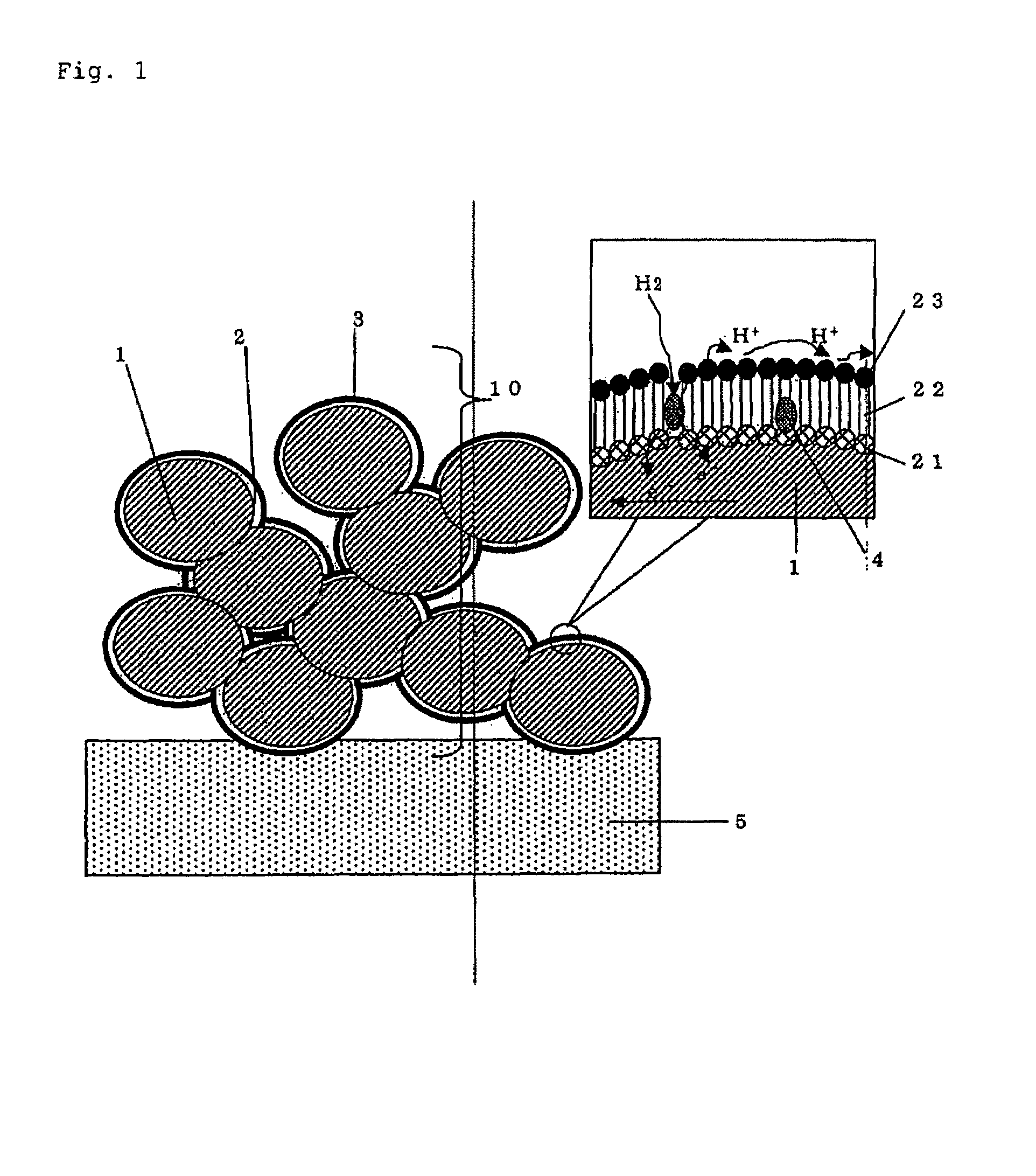
[0109]FIG. 1 illustrates an example of an embodiment of the porous electrode of the present invention.

[0110]The porous electrode 10 of the present invention consists of a porous material 1 having electron conductivity and composed of conductive particles. A surface 3 with proton affinity attributable to proton affinity groups 23 is formed on the porous material, via a spacer 2. This spacer 2 is adsorbed to the porous material 1 at a portion 21 (affinity portion) with high affinity to the porous material, and a catalyst 4 in the form of microparticles is contained within this chain monomolecule 22.

[0111]When this porous electrode is used as an electrochemical element, as shown in the example of a fuel cell in FIG. 3, the porous electrodes 10 can be disposed across from each other with a proton-conductive solid electrolyte 5 in between, the electrodes can be connected to an external circuit, and a fuel can be supplied to the electrodes. The catalyst 4 used in the porou...

embodiment 2

(2) EMBODIMENT 2

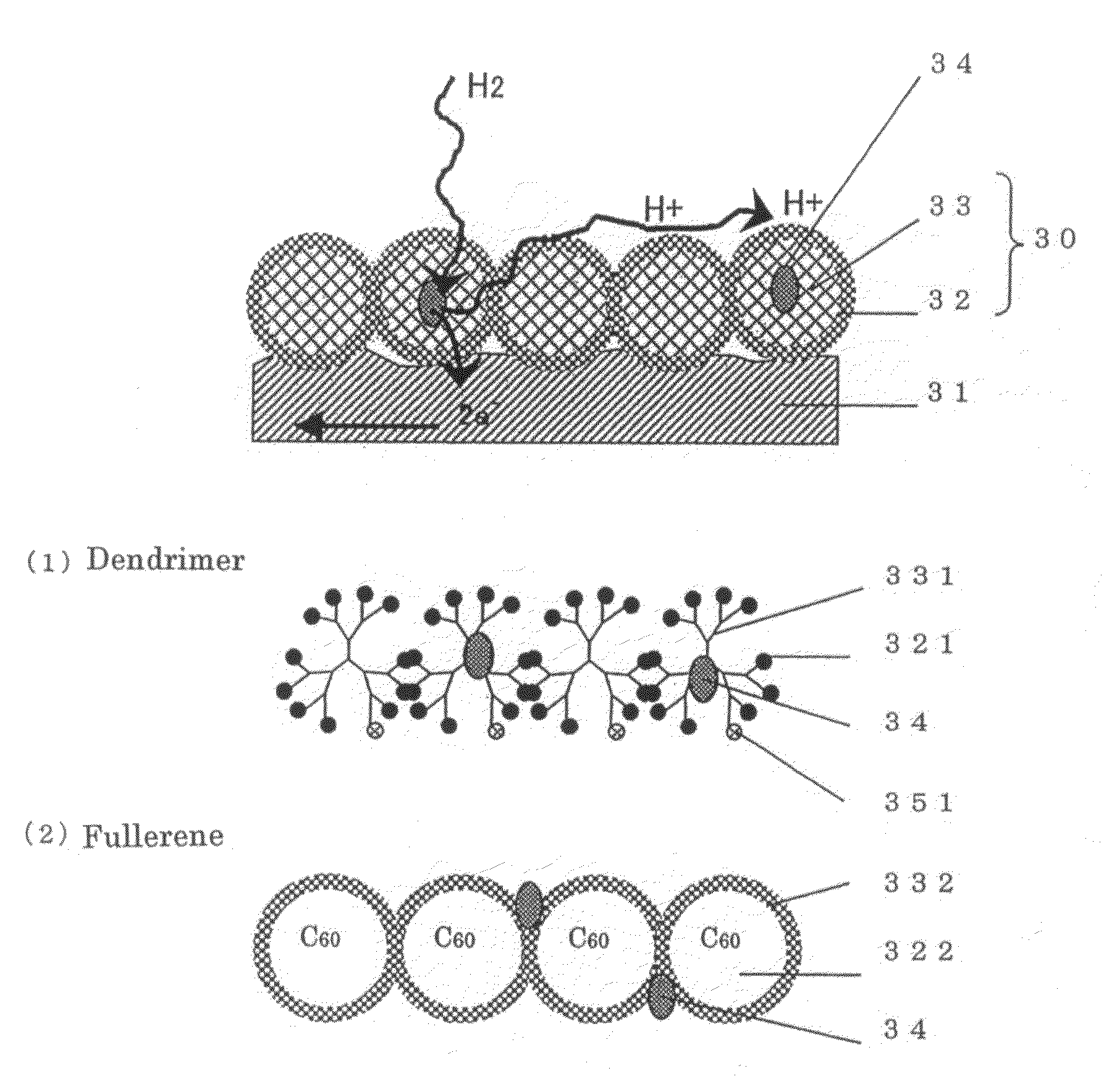
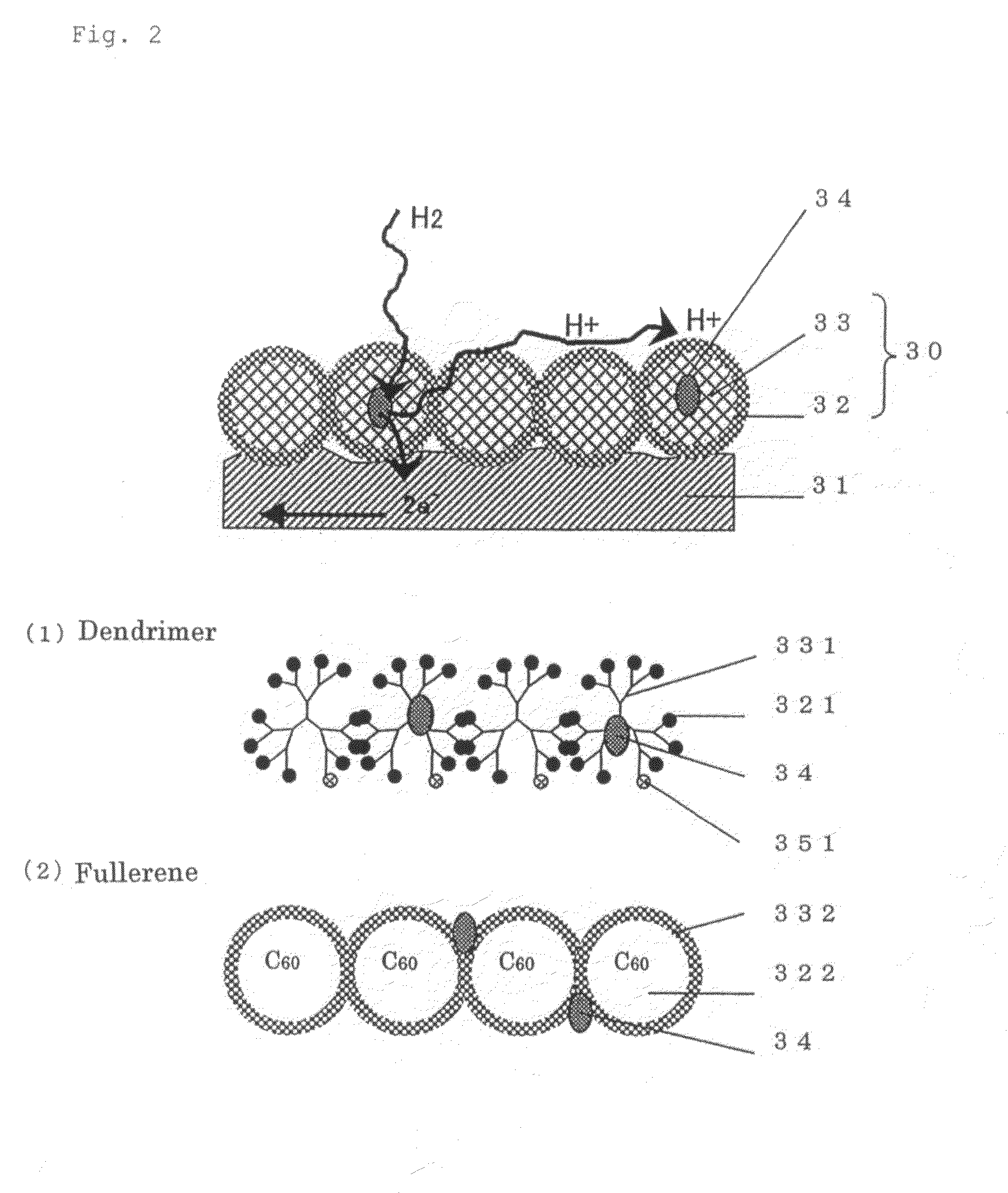
[0115]The another structure of the surface 31 portion of the porous material having electron conductivity in the porous electrode of the present invention will be described through reference to FIG. 2.

[0116]In contrast with the structure consisted of an organic layer of chain molecules in Embodiment 1, the same advantages can be obtained with a spacer 30 of spherical molecules as in Embodiment 2. The spacer 30 of spherical molecules is composed of a spacer component 33 and a proton affinity group component 32. The microparticles of a catalyst 34 are disposed inside the organic layer or between the spherical molecules.

[0117]A dendrimer of spherical molecules produced by the dendritic growth of a polymer, as well as spherical carbon such as carbon 60 and carbon 70, are preferable as these spherical molecules. These spherical molecules are suited to the object of the present invention because they facilitate the introduction of proton affinity groups or groups with affi...

embodiment 3

(3) EMBODIMENT 3

[0120]Another structure of the porous electrode of the present invention will be described through reference to FIG. 5.

[0121]When the porous electrode is used for an electrochemical element, the porous electrode 10 constituted as shown in Embodiment 1 or 2 is joined to the proton-conductive solid electrolyte 5. The empty space in the porous electrode 10 contributes to the electrode reaction with the catalyst through diffusion of fuel, and also conducts protons at the surface 3. If this space could handle both of the functions discussed above, there would be no need for voids in the porous material. Specifically, tiny voids are produced in a filler space 300 that fills with the spherical molecules having proton affinity groups on their surface. The hydrogen is able to diffuse into these voids, and therefore reaches the catalyst and undergoes an electrode reaction. Also, with this structure, the protons are moved not only at the surface 3, but also in the filler space ...


PUM

PropertyMeasurementUnit
porosityaaaaaaaaaa
porosityaaaaaaaaaa
specific surface areaaaaaaaaaaa

Abstract

The primary object of the present invention is to provide an electrode with which an efficient electrode reaction will occur. The present invention relates to a porous electrode which is an electrode composed of a porous material having electron conductivity, wherein (1) the porous material comprises a three-dimensional skeleton, (2) a substance having one or more proton affinity groups is present on all or part of the three-dimensional skeleton surface, and (3) a catalyst for separating hydrogen into protons and electrons is further included, with the catalyst being supported on the substance.

Description

[0001]This application is a continuation under 111(a) of PCT / JP03 / 013979, filed on Oct. 31, 2003.TECHNICAL FIELD[0002]This invention relates to a porous electrode used in electrochemical elements for cells, capacitors, and so forth. In particular, the invention is directed to an electrochemical element such as a fuel cell, air cell, hydrolysis apparatus, gas sensor, contaminant gas removal apparatus, and so forth in which this porous electrode is used as a gas diffusion electrode together with a reaction gas and an electrolyte.BACKGROUND ART[0003]Growing concern about the global environment issue has led to advances in the conservation of resources and energy. Considerable progress has been made in the development of energy resources that can be used as renewable “clean” energy, and systems thereof. Fuel cell systems in which hydrogen serves as the energy source have a particularly wide range of applications, such as in alternative automobile engine technology, distributed power sou...

Claims


Application Information

Patent Timeline
Patent Type & Authority Patents(United States)
IPC IPC(8): H01M4/86C25B11/03C25B11/12H01M4/88H01M4/90H01M4/96H01M8/02H01M8/04H01M8/10H01M8/12
CPCH01M4/8605H01M4/925H01M4/8652H01M4/92Y02E60/50
Inventor SUZUKI, MASA-AKI
Owner PANASONIC CORP
Why Eureka
Try Eureka