
Throttle plate for use with internal combustion engine

Active Publication Date: 2010-02-23
K&N ENGINEERING INC
View PDF9 Cites 10 Cited by
  • Summary
  • Abstract
  • Description
  • Claims
  • Application Information

AI Technical Summary

Benefits of technology

[0007]This invention is a throttle plate for use with internal combustion engines that effectively increases horsepower and improves fuel efficiency in internal combustion engines. The throttle plate of this invention comprises a plate having apertures to accommodate the pre-existing connectors and a perimeter that corresponds to connections between, and the geometry of, the carburetor or throttle body and intake manifold of the vehicle on which it will be installed. The plate fits between the carburetor or throttle body and intake manifold and defines at least one airflow hole corresponding to the airflow path in the carburetor or throttle body. If there are multiple airflow paths between the carburetor or throttle body and intake manifold, then there will be multiple airflow holes. One or more vanes integral with the plate extend radially from the perimeter of each airflow hole toward its center. The vanes can be a variety of shapes, including helical and inclined, and extend into the airflow hole only to the extent they do not obstruct operation of the throttle valve in the throttle body.

Problems solved by technology

Because the intake hoses are distant from the intake ports of the engine and do not work in relation to the throttle valve, these vortex generators have little or no effect.
Rather, these vortex generators actually obstruct airflow, leading to increased drag and reduced efficiency.
Unfortunately, while effective, current throttle body spacer designs are cumbersome to install or not optimized for maximum benefit at part throttle.
Thinner spacers are available for motorcycles; but those designs do not account for the protruding throttle valve and are not optimized for maximum effectiveness at part throttle positions.

Method used


Image

  • Throttle plate for use with internal combustion engine
  • Throttle plate for use with internal combustion engine
  • Throttle plate for use with internal combustion engine

Examples


Embodiment Construction

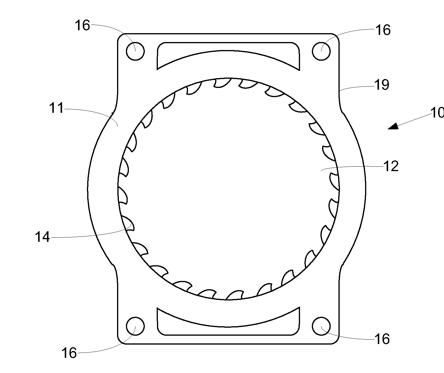
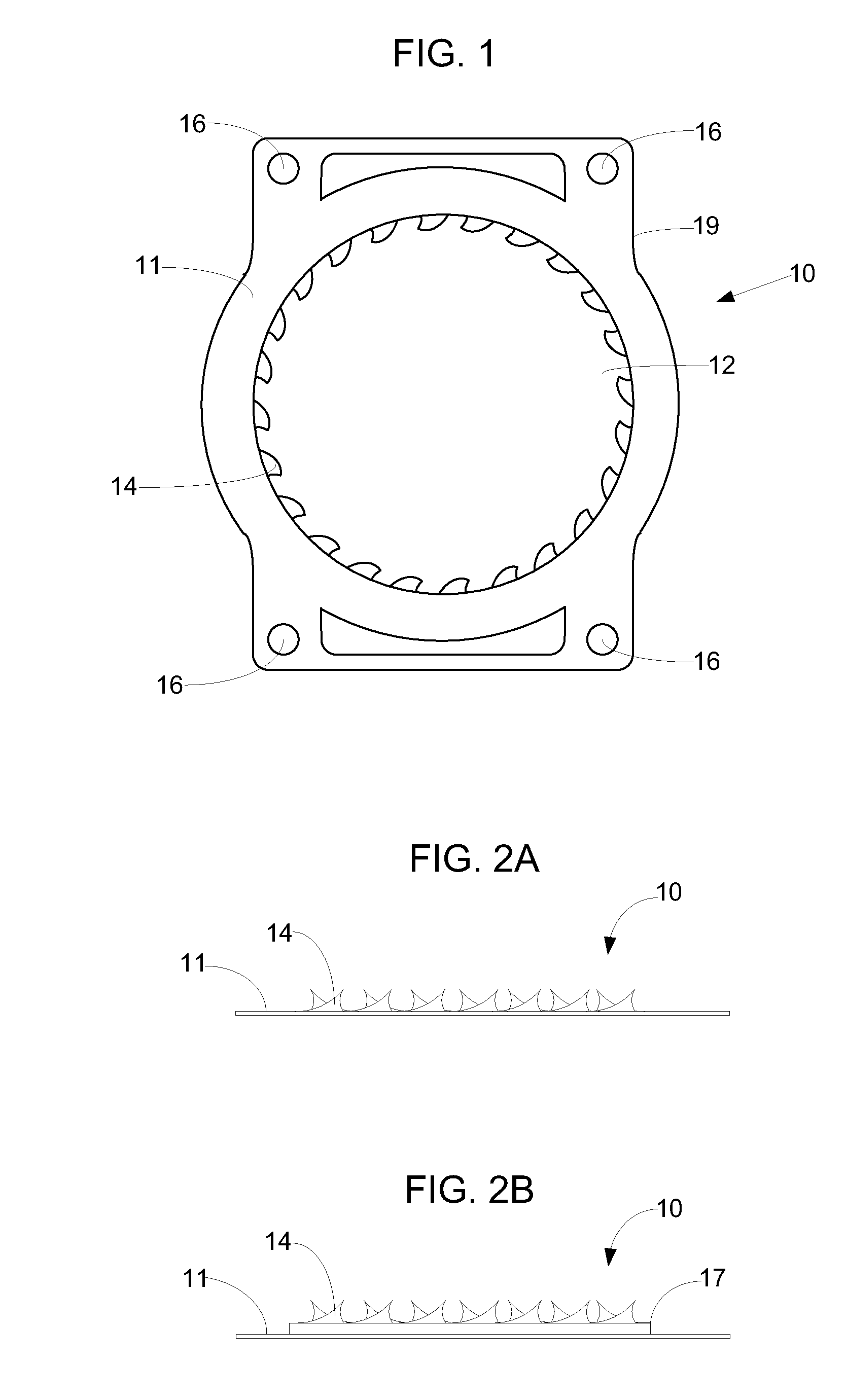
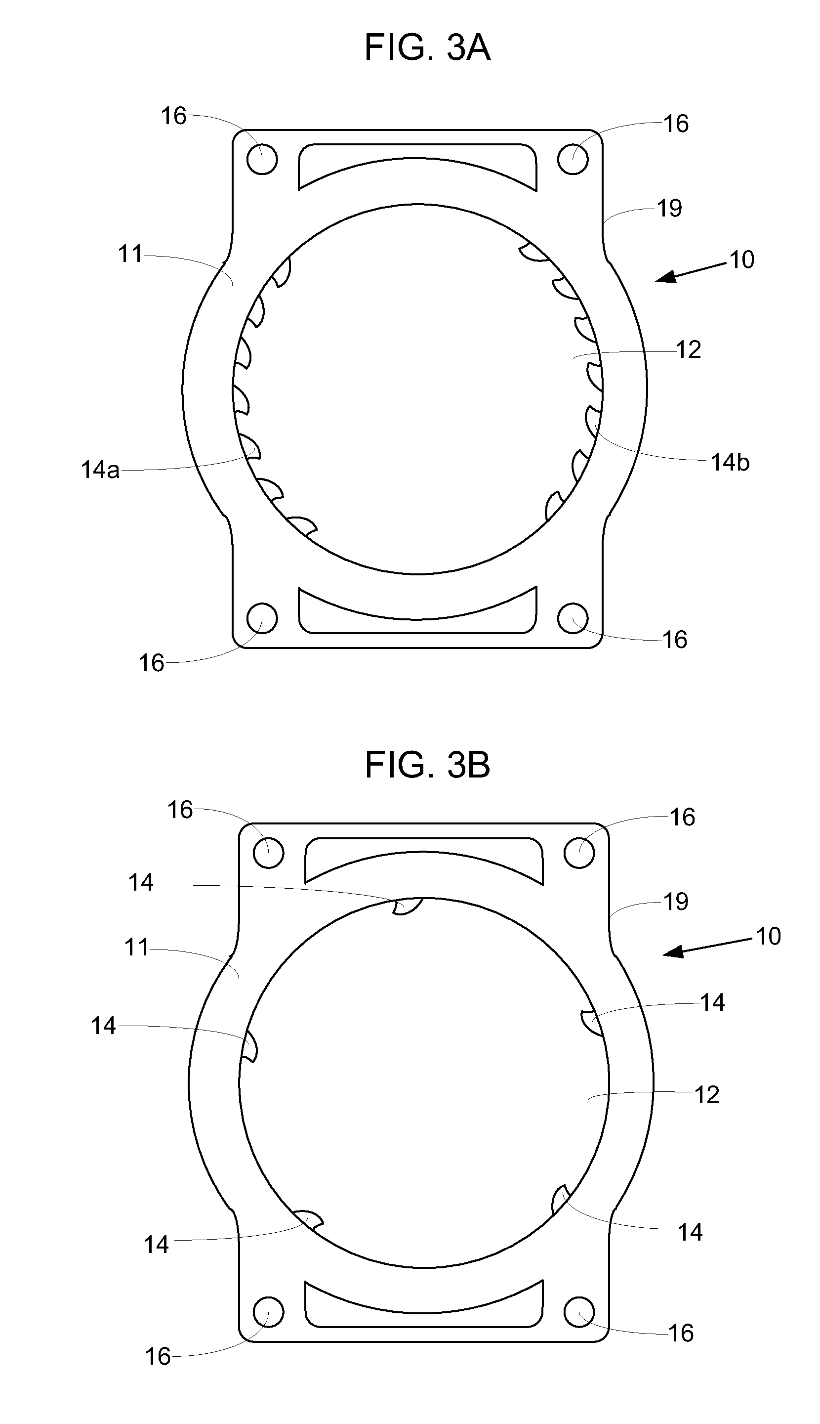
[0021]This invention is a throttle plate 10 for increasing horsepower and improving fuel efficiency in internal combustion engines. A preferred embodiment of the throttle plate 10 of this invention is shown in FIGS. 1 and 2A. The throttle plate 10 includes a plate 11 that defines an airflow hole 12, and one or more connection holes 16. Vanes 14 are preferably integral with plate 11 and extend from the circumference of airflow hole 12 toward the center of airflow hole 12. Plate 11 is further defined by perimeter 19. FIG. 2B illustrates a second embodiment of this invention incorporating a neck 17 to offset vanes 14 from the plate 11.

[0022]Plate 11 can be manufactured from any relatively thin material. Traditionally, throttle body spacers are approximately one inch thick and require extra connectors and spacers to properly position the spacer between the throttle body and intake manifold. In contrast, plate 11 of this invention is of a thickness that does not require additional connec...


PUM


Abstract

A throttle plate for use with internal combustion engines comprised of a relatively thin piece of material so that installation of the throttle plate between the carburetor or throttle body and intake manifold of a vehicle does not require additional brackets or components to correct throttle cable linkage length or geometry. The throttle plate comprises a plate having apertures to accommodate pre-existing connectors and a perimeter that corresponds to connections between, and the geometry of, the carburetor or throttle body and intake manifold. The plate fits between the carburetor or throttle body and intake manifold and defines at least one airflow hole corresponding to the airflow path in the carburetor or throttle body. If there are multiple airflow paths between the carburetor or throttle body and intake manifold, then there will be multiple airflow holes. One or more vanes integral with the plate extend radially from the perimeter of each airflow hole toward its center. The plurality of vanes can be a variety of shapes, including helical and inclined, and extend into the airflow hole only to the extent they work in proximity of the throttle valve(s) and do not obstruct operation of the throttle valve in the throttle body. As air flows from the throttle valve(s) through the throttle plate and into the intake manifold, the vanes redirect laminar airflow into turbulent airflow.

Description

FIELD OF INVENTION[0001]This invention generally relates to the field of air intake systems for vehicle internal combustion engines. In particular, this invention relates to a throttle plate designed to increase horsepower and fuel efficiency in internal combustion engines.BACKGROUND[0002]Increasing power and improving fuel efficiency of internal combustion engines is particularly desirable across the population of automobile drivers. One method of increasing power and improving fuel efficiency is to increase the volume of dense air flowing into the combustion chamber of a vehicle's engine. Throttle body spacers, such as the Poweraid® TBS available from Airaid, are designed to create a vortex that spins air to be combusted while maintaining the same pressure differential, which ultimately improves engine efficiency. The greater the efficiency level of the intake system, the greater horsepower output there will be.[0003]Generally, air enters a vehicle's fuel system at the airbox or a...

Claims


Application Information

Patent Timeline
IPC IPC(8): F02B31/00F02M29/00
CPCF02M29/06F02M29/14
Inventor LEVITZ, JOHNENLOE, SAM
Owner K&N ENGINEERING INC
Learn More