Container gripping device having contact elements for braking

a technology of contact elements and gripping devices, which is applied in the direction of load-engaging elements, transportation and packaging, etc., can solve the problems of increased wear, increased load which occurs when the frame of the gripping device lands on the container, and in principle costly time for the transporter, and achieves considerable damping and large form.

Inactive Publication Date: 2010-02-23
STINIS BEHEER
View PDF23 Cites 5 Cited by
  • Summary
  • Abstract
  • Description
  • Claims
  • Application Information

AI Technical Summary

Benefits of technology

[0020]In order to absorb a part of the energy during braking of the frame, the device preferably has damping means arranged between the frame and the or each contact element. When these damping means are at least partly accommodated in an elevation formed on the frame, they can take a relatively large form, and thus produce a considerable damping without protruding and being exposed to damage.

Problems solved by technology

Since during loading and unloading of containers the transport means on which or in which the containers are supplied and / or removed necessarily stands or lies still, the time involved herein is in principle costly for the transporter.
Owing to these higher speeds the loads which occur when the frame of the gripping device lands on the container are also becoming increasingly larger.
These greater loads result in increased wear and thus a reduction in the life span of the different components of the device, while in addition the high loads result in considerable noise production, both during landing of the frame on the container and at the beginning of the hoisting movement, when the device is not yet fully loaded.
This noise results in nuisance, particularly in built-up areas.
These known spreaders have the drawback that space is required for guiding of the housing in the frame, whereby the outer dimensions of the frame become larger at the position of the corners, and the frame will therefore protrude outside the container(s).
All lateral loads will hereby be absorbed by the frame, so that the chance of damage to the gripping device increases.
Finally, owing to the increase in the dimensions of the frame in all directions, the chance of damage thereto is increased disproportionately, since a spreader in loaded state, particularly when it is hoisting a plurality of containers simultaneously, will never hang perfectly horizontally.
A slightly inclining position, particularly at the start of a hoisting movement, can result in the spreader becoming jammed, for instance in a cell of a container ship, whereby very high loads will occur which will soon result in damage.

Method used


Image

  • Container gripping device having contact elements for braking
  • Container gripping device having contact elements for braking
  • Container gripping device having contact elements for braking

Examples


Embodiment Construction

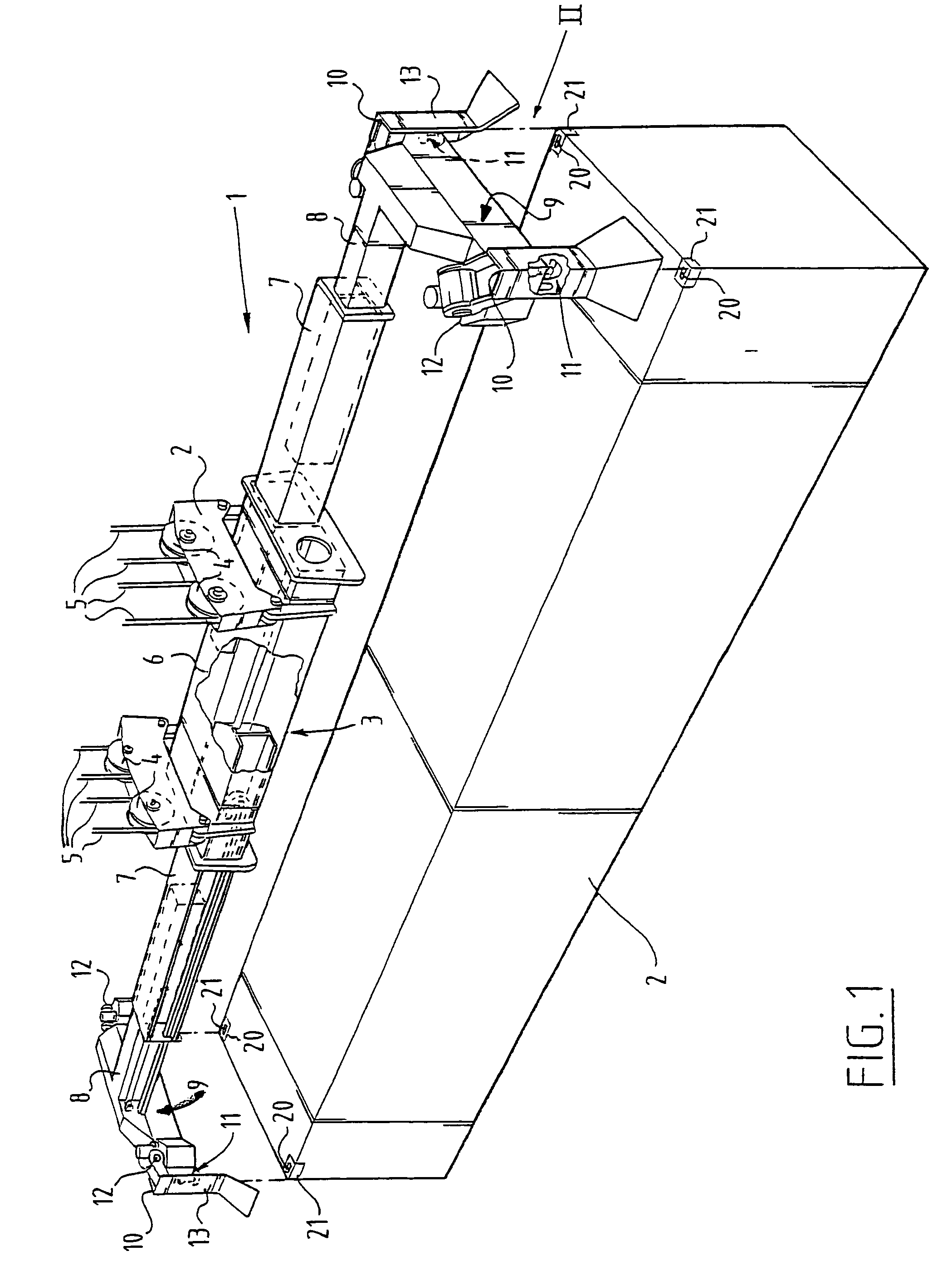
[0025]A gripping device 1 (FIG. 1) for picking up a container 2 from above is formed by a frame 3 which is suspended from a number of cables 5 trained over pulleys 4. In the shown embodiment the frame 3 is embodied telescopically, with a main body 6 and two sets of inner and outer telescopic arms 7,8, although it will be apparent that the invention can be applied equally well in a fixed frame.

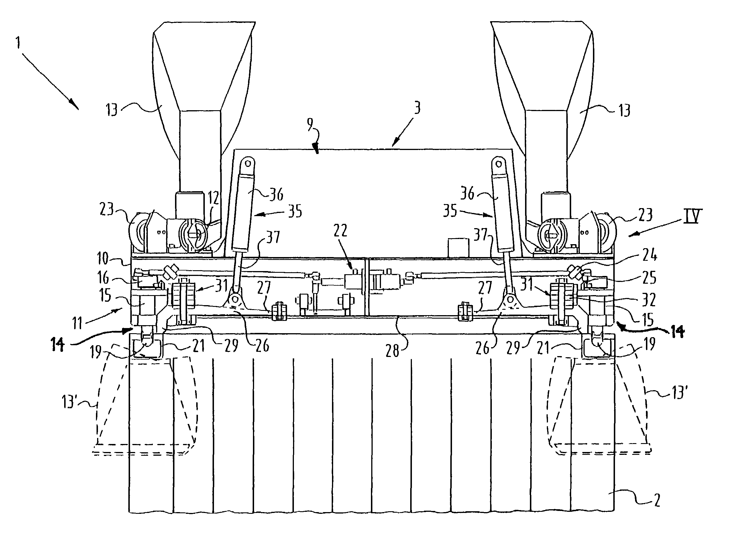
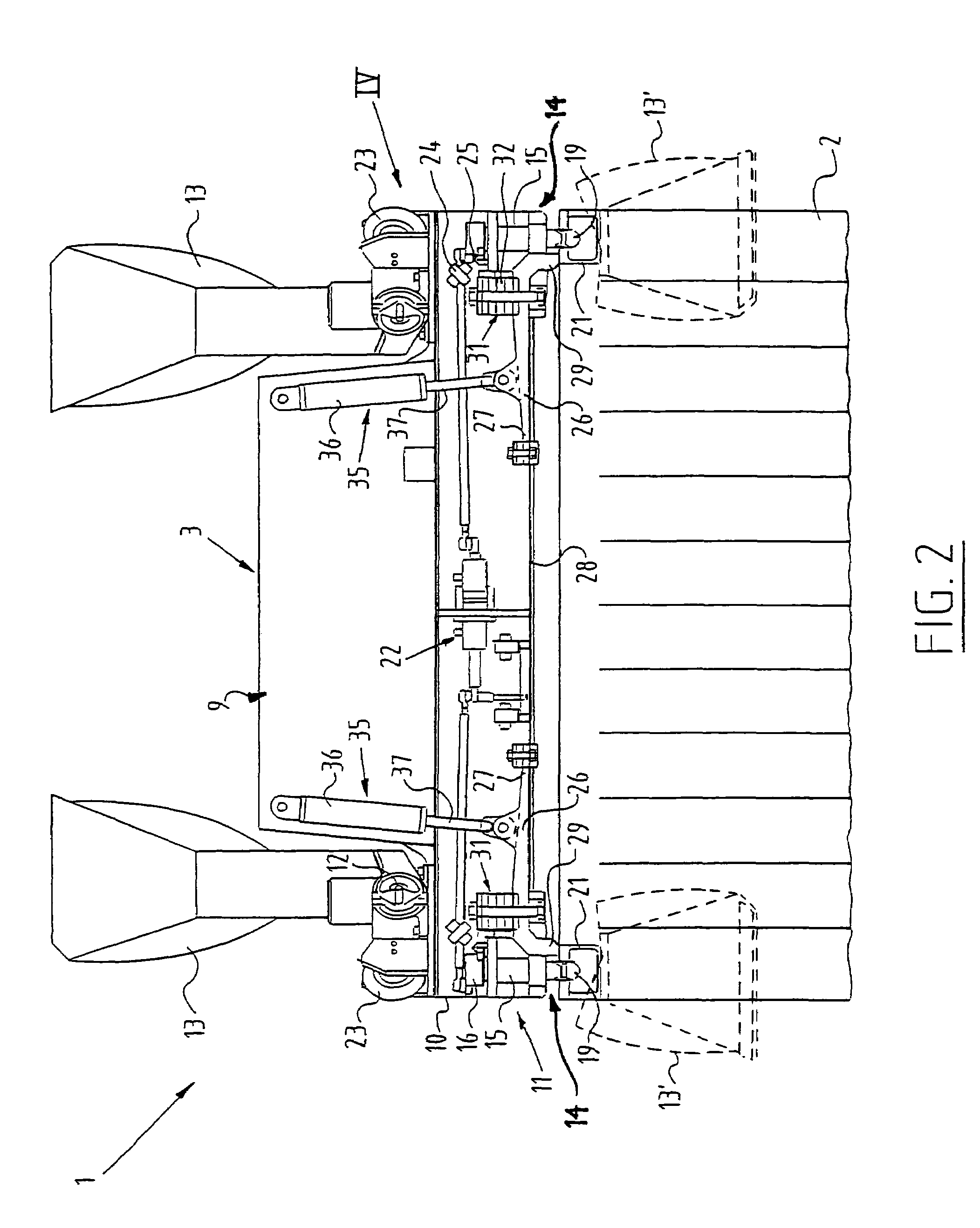
[0026]On the end of each outer telescopic arm 8 is arranged a relatively high cross beam 9 which in each case has on its corners 10 gripping means in the form of a twist-lock 11. In addition, centring members or flippers 13 pivotable on shafts 12 are also placed on the corners.

[0027]Each twist-lock 11 is formed by a hammer-head bolt 14, the shank 18 of which is received in a guide sleeve 15. At the top the shank 18 of hammer-head bolt 14 is fastened in an operating sleeve or crank 16, which is connected in turn to an operating mechanism 22. Hammer-head bolt 14 can be rotated around an axis 17 b...


PUM


Abstract

A device for gripping containers from above, which includes a frame which has a number of corners, twist-locks arranged close to each of the corners of the frame for gripping an upper corner of the containers, and contact elements connected to the frame, which elements are biased to a position located at least partly under the frame and which are adapted to brake the movement of the frame in the vicinity of a container when the frame is placed on the container. The presence of these contact elements allows loads on the frame to be reduced and noise nuisance to be minimized. The contact elements, which may be arranged in or on the frame and may protrude through openings formed in the frame, may be elastically deformable or may be pivotally connected to the frame. Compression springs and/or hydraulic cylinders may be arranged between the frame and the contact elements.

Description

BACKGROUND OF THE INVENTION[0001]1. Field of the Invention[0002]The invention relates to a device for gripping containers from above.[0003]2. Description of the Related Art[0004]Container gripping devices are generally known and, because the frame is generally adjustable, are usually referred to as spreaders.[0005]Spreaders are applied for gripping containers during hoisting thereof, for instance during loading or unloading of container ships. Standard containers are provided for handling and anchoring thereof with gripping points on the corners, so-called corner castings. These corner castings form reinforced corner points in which an elongate opening is formed. The gripping means of the frame, usually in the form of a so-called twist-lock, can grip in these openings.[0006]A twist-lock consists here of a pin or shank with a hammer head on an outer end, which pin is received at its other outer end in a bush or sleeve, which is connected in turn to a rotating operating mechanism. The...

Claims


Application Information

Patent Timeline
Patent Type & Authority Patents(United States)
IPC IPC(8): B66C1/66
CPCB66C1/663
Inventor STINIS, CORNELIS
Owner STINIS BEHEER
Why Eureka
Try Eureka