Power connector assembly

a technology of power connectors and connectors, applied in the direction of securing/insulating coupling contact members, coupling device connections, incorrect coupling prevention, etc., can solve the problems of significant change of electrical characteristics, reduced firmness and solidity of insulative housings, and risk of bending portions of u-shape plates , to achieve the effect of improving heat dissipation structur

Inactive Publication Date: 2010-02-23
ALLTOP ELECTRONICS SU ZHOU
View PDF6 Cites 31 Cited by
  • Summary
  • Abstract
  • Description
  • Claims
  • Application Information

AI Technical Summary

Benefits of technology

[0010]Accordingly, an object of the present invention is to provide a power connector assembly having an improved heat-dissipating structure.
[0011]Another object of the present invention is to provide a power connector assembly having improved terminals with higher electrical characteristics and simplified manufacturing process.

Problems solved by technology

However, the current flows in a power circuit are relatively high which may cause significant change of the electrical characteristics.
Firstly, the heat-dissipate holes are only formed on the top wall of the insulative housing, which will limit the dissipating direction of heat only on one upward direction.
Secondly, firmness and solidity of the insulative housing will decrease if too many heat-dissipating holes are formed in the top wall of the housing.
The bending portion of the U-shape plate has a risk of chapping during its manufacturing process, which will influence electrical characteristics of the terminal during power transmission.
Moreover, when soldering the terminal to the circuit board, the high temperature of the soldering process will release stress of the bending portion, which will lead to mismatch of the solder legs of the terminal with the solder hole in the circuit board, and will cause failure of the soldering process.

Method used


Image

  • Power connector assembly
  • Power connector assembly
  • Power connector assembly

Examples


Embodiment Construction

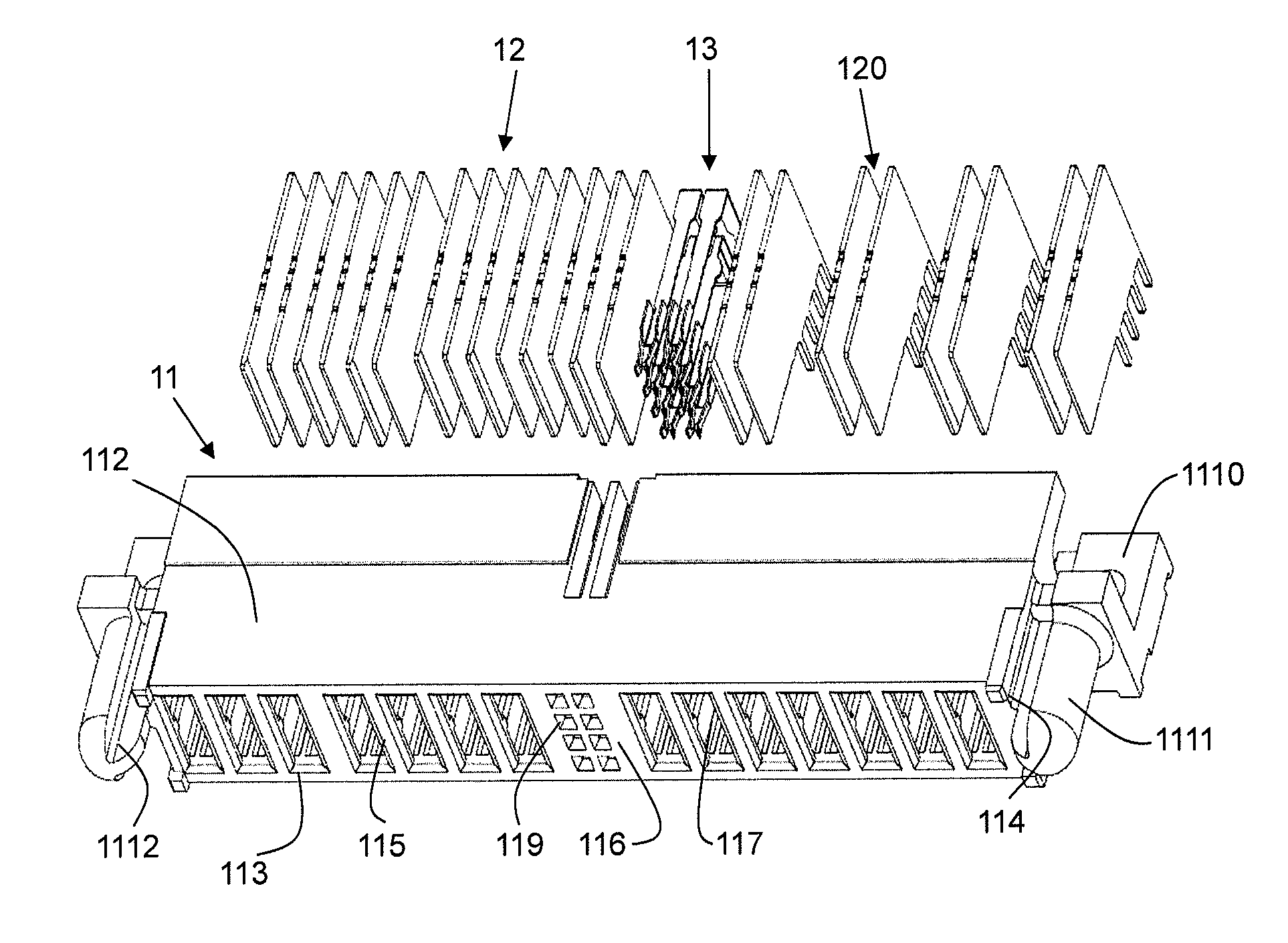
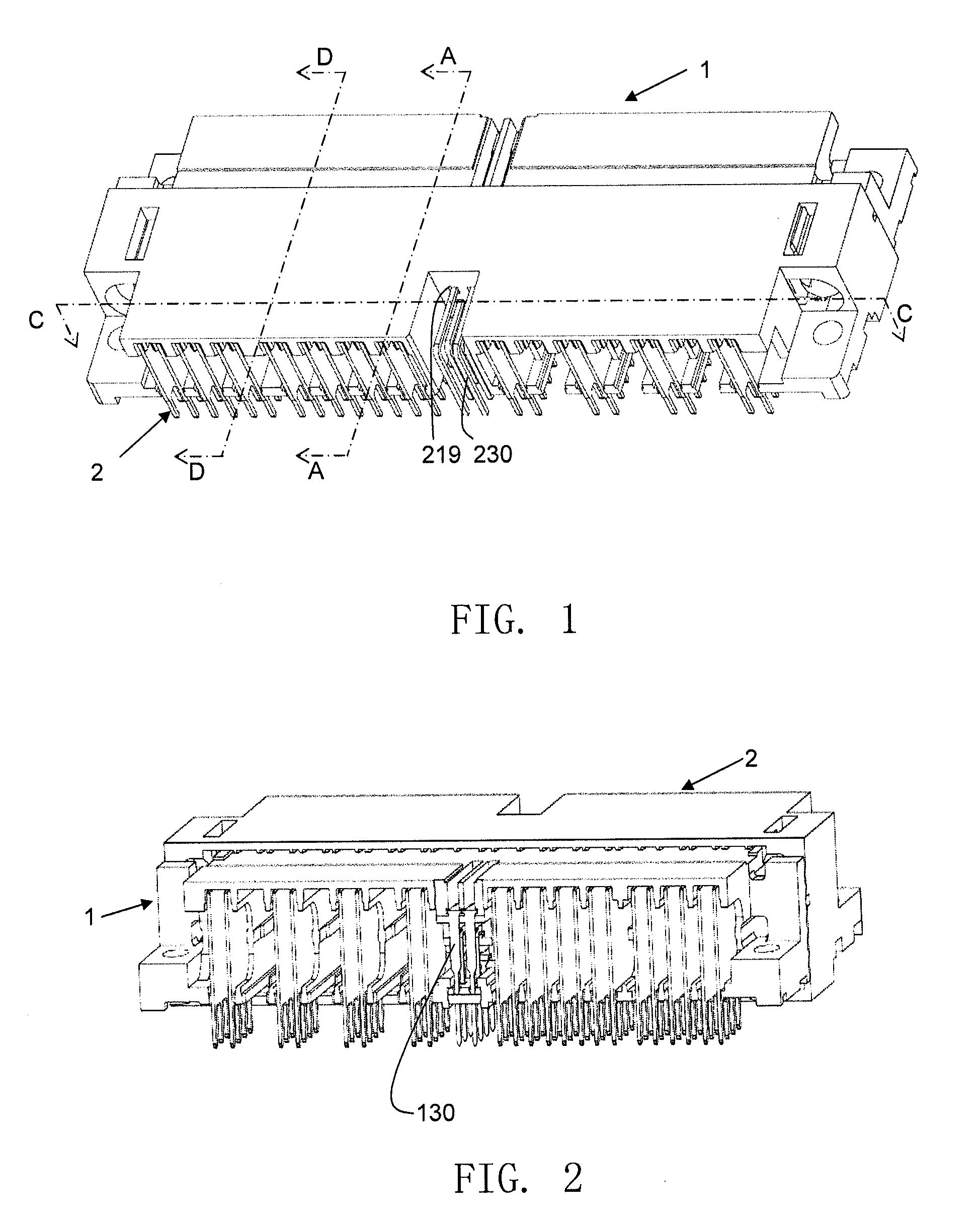
[0036]Referring to FIGS. 1 and 2, a power connector assembly in accordance with a preferred embodiment of the present invention comprises a first power connector having a first insulative housing with a plurality of first power terminals secured therein and a second power connector having a second insulative housing with a plurality of second power terminals secured therein, the first power connector mates with the second power connector so as to transmit high voltage and high current power via the first and the second power terminals provided therein. In the present embodiment, the first connector is a plug connector 1 having a plurality of plug terminals (also named as male terminals) secured therein and the second connector is a receptacle connector 2 having a plurality of receptacle terminals (also named as female terminals) secured therein. The plug connector 1 and the receptacle connector 2 are respectively mounted onto one circuit board, and power can be transferred between t...


PUM


Abstract

A power connector assembly is provided which comprises a plug connector and a mating receptacle connector. The plug connector includes an insulative plug housing having a plurality of passageways divided by division walls and a plurality of plug terminals accommodated in the corresponding passageways of the plug housing. The receptacle connector includes an insulative receptacle housing having a receiving space for receiving a part of the plug housing inserted therein and a plurality of receptacle terminals accommodated in the receptacle housing for mating with the plug terminals. Airflow channels are formed between the outer surface of the part of the plug housing in the receiving space and the inner surface of the receiving space for dissipation of heat.

Description

CROSS REFERENCE TO RELATED APPLICATION[0001]This application claims the benefit of Chinese Patent Application No. 200810020593.2, filed on Feb. 4, 2008 in Chinese Intellectual Property Office, the disclosure of which is incorporated herein by reference.BACKGROUND OF THE INVENTION[0002]1. Field of the Invention[0003]The present invention relates to a power connector assembly, and more particularly to an assembly of a receptacle connector and a plug connector interconnecting two separate circuit boards for transmission of power therebetween.[0004]2. The Prior Arts[0005]When designing an electronic circuit, the designer generally will concern two basic parts, i.e., the part of logic (or signal) and the part of power. Because of the current flows through a logic circuit are usually low, the circuit designer needs not to consider the effect of status (for example, temperature) on electrical characteristics (for example, circuit component impedance) when designing a logic circuit. However...

Claims


Application Information

Patent Timeline
Patent Type & Authority Patents(United States)
IPC IPC(8): H01R13/00H01R12/57
CPCH01R12/7088H01R12/58H01R23/7073H01R12/724
Inventor CHENG, I-HUNGTAI, HUNG-CHI
Owner ALLTOP ELECTRONICS SU ZHOU
Why Eureka
Try Eureka