Air treatment devices with use-up indicators

a technology of use-up indicators and air treatment devices, which is applied in the direction of material analysis, space heating and ventilation, and discharging of containers from pressure vessels, etc., can solve the problems of inaccurate information, low cost of producing these devices, and low reliability and

Active Publication Date: 2010-03-02
SC JOHNSON & SON INC
View PDF21 Cites 49 Cited by
  • Summary
  • Abstract
  • Description
  • Claims
  • Application Information

AI Technical Summary

Benefits of technology

[0021]U.S. Pat. No. 6,031,967 generally describes units designed to permit dispensing air treatment chemicals from an internal well upon heating after removal of a peel-off lid cover. The well can be made from a heat-resistant plastic such as polyethylene terephthalate, and be provided with an integral surrounding upper flange. In the present invention, the lid can be a laminate whose outer layers are suitable to receive advertising and use information, and provide long term sealing. The inner layers (which are separable from the outer layers) can provide the permeable layer structure. One possible lid would have an outer polyester layer, under which is positioned a low density polyethylene layer, under which is positioned an aluminum foil layer, under which is positioned polypropylene, under which is positioned low density polyethylene material.
[0027]The substrate and indicator unit can be simultaneously replaced when they are both mounted on a cartridge unit. The cost of producing these devices is surprisingly low. These devices are reliable and effective for a variety of air treatment purposes.

Problems solved by technology

A disadvantage associated with such devices is that the consumer may not be aware of when the substrate has been exhausted.
While it is possible to include a suggested useful life on the packaging for such products, consumers may not read or remember that information.
Further, given the wide range of heater performance to which such substrates may be exposed, providing suggested useful life information may not be accurate.
This can lead to use of the substrate after its effective useful life (with resulting consumer dissatisfaction).
Alternatively, it can lead to premature disposal of a still useful substrate (and thus unnecessary cost and waste).
Further, coordinating the visual cue provided by the volatization of the indicator chemical with the rate of use of the air treatment chemical was difficult, particularly because both the indicator and the treatment chemical were being exposed to similar conditions, even though they might have different dispensing properties.
However, the candle system is not applicable to non-flame environments, and the use of limited duration bulbs can be relatively expensive.
However, structures for using this concept were not described in detail in this patent, nor were ways of creating a joint replaceable cartridge using these features, nor were ways of positioning the indicator at a different distance from the heater than the air treatment chemical, nor were ways of providing additional air treatment functionality.

Method used


Image

  • Air treatment devices with use-up indicators
  • Air treatment devices with use-up indicators
  • Air treatment devices with use-up indicators

Examples


Embodiment Construction

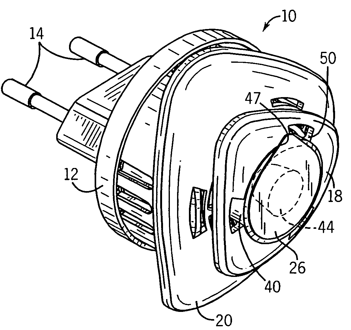
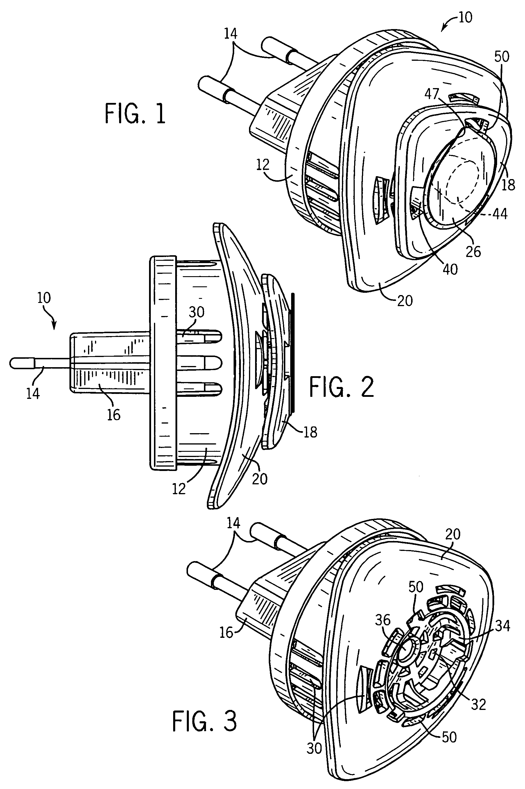
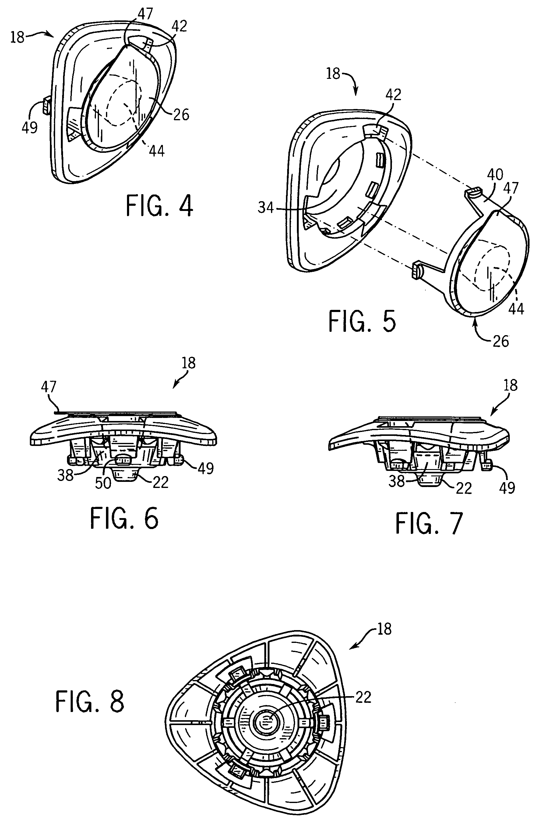
[0043]Referring first to FIGS. 1-3, a preferred embodiment of an air treatment chemical dispensing device 10 of the present invention is shown. The device 10 has a housing 12 having electrical prongs 14 at a rear end 16 and a cartridge unit 18 at an opposing forward end 20. The device is most preferably plugged into an electric socket on a vertical wall. Hence, the directional terms in this patent are used with that type of installation in mind.

[0044]However, appropriate electric sockets on horizontal or other surfaces may also be used to provide power. Thus, the terms such as “front”, “rear”, “upper”, “lower”, and “side” should be interpreted in an analogous manner when the devices are used for that type of installation.

[0045]It should be noted that the prongs 14 shown in the figures are merely for purposes of example. Cylindrical prongs of this type are suitable for linking to electric power in some countries. However, in other countries blade prongs, or mixtures of blades, cylind...


PUM

PropertyMeasurementUnit
volatileaaaaaaaaaa
color changeaaaaaaaaaa
thermochromicaaaaaaaaaa

Abstract

Disclosed are devices for dispensing air treatment chemicals. There is a substrate bearing a first volatile air treatment chemical that is capable of being dispensed from the substrate when the substrate is heated, and an indicator unit holding a volatile indicator chemical separate from the first volatile air treatment chemical such that the volatile indicator chemical is capable of being dispensed from the unit when the unit is heated. The extent of dispensing of the first volatile air treatment chemical can be indicated by a visible cue whose appearance results from the dispensing of the volatile indicator chemical. In one form the unit also holds a second air treatment chemical. In another the indicator unit is a replaceable cartridge positionable more remote from the heater than the substrate.

Description

CROSS-REFERENCE TO RELATED APPLICATIONS[0001]Not applicable.STATEMENT REGARDING FEDERALLY SPONSORED RESEARCH / DEVELOPMENT[0002]Not applicable.BACKGROUND OF THE INVENTION[0003]The present invention relates to devices that dispense a volatile air treatment chemical by heating a substrate impregnated with, or coated with, the chemical. More particularly it relates to indicators used with such devices to indicate when the treatment chemical has been used up.[0004]Substrates (particularly porous substrates) have previously been used as carriers for air treatment chemicals such as insect control agents (insecticides, insect repellents, insect growth regulators, insect attractants, synergists, etc.), fragrances and deodorizers. See e.g. U.S. Pat. Nos. 5,111,477; 5,647,052 and 6,663,838. The disclosure of these patents, and of all other patents referred to herein, are incorporated by reference as if fully set forth herein.[0005]Upon heating the substrate a volatile air treatment chemical is ...

Claims


Application Information

Patent Timeline
Patent Type & Authority Patents(United States)
IPC IPC(8): A61L9/01A61L9/02A61L9/03
CPCA01M1/2077A61L9/03G01N31/229Y10S514/957
Inventor ADAIR, JOEL E.DAVIS, BRIAN T.ANANTH, GOPAL P.SZYMCZAK, THOMAS J.
Owner SC JOHNSON & SON INC
Why Eureka
Try Eureka