Camera

a technology for cameras and cameras, applied in the field of cameras, can solve the problems of increased electric power consumption, dew generation on the inside surface of protective plates, and increase in cost due to glass heaters, and achieve the effects of reducing electric power consumption, small size, and convenient configuration

Inactive Publication Date: 2010-03-02
SONY CORP
View PDF28 Cites 10 Cited by
  • Summary
  • Abstract
  • Description
  • Claims
  • Application Information

AI Technical Summary

Benefits of technology

[0009]It is an object of the present invention to provide a camera in which dewing does not occur on transparent members in an optical path for introducing picture rays.
[0011]It is a further object of the invention to provide a camera in which prevention of dewing by electric heating is not needed.
[0020]According to the embodiment as above, it is possible to produce a camera in which it is difficult for dewing to occur, particularly on the inside of the lenses. In addition, since the lens block can be so structured as to be separable from the camera main body, a camera having a different angle of view from the original camera can be easily configured by simply replacing the original lens block by another lens block having the different angle of view.
[0021]Besides, since there is no need for a glass heater or a moisture absorbent for preventing dewing, the cost for such a dewing-preventive unit is precluded, there is no need for space for laying out such a glass heater or moisture absorbent or a peripheral equipment thereof, and the camera can therefore be made small in size. In addition, since a glass heater is not needed, electric power consumption is reduced, the rise in the temperature inside the camera is suppressed, and bad influences on semiconductor component parts are restrained. Further, generation of water vapor from a moisture absorbent due to a rise in the inside temperature, and the resultant dewing, can be obviated. Furthermore, there is no fear that scum or dust might be generated from a moisture absorbent to produce bad effects on the image.

Problems solved by technology

Such an automotive camera according to the related art has the defect of generation of dewing on the inside surface of the protective plate.
However, this leads to an increase in cost due to the glass heater 13, or an increase in electric power consumption due to the power consumption by the glass heater 13, and the rise in the temperature inside the camera produces bad influences on the electric component parts, particularly semiconductor devices inclusive of the CCD 3, which are present inside the camera.
In this case, however, there is the problem that the moisture absorbed into the moisture absorbent as time passes is discharged as water vapor upon a temperature rise due to a camera operation, with the result of dewing, or that the moisture absorbent generates dust or debris.
Furthermore, the moisture absorbent 15 leads to an increase in cost and to the need to secure a space for arranging the moisture absorbent 15.

Method used


Image

  • Camera
  • Camera
  • Camera

Examples


Embodiment Construction

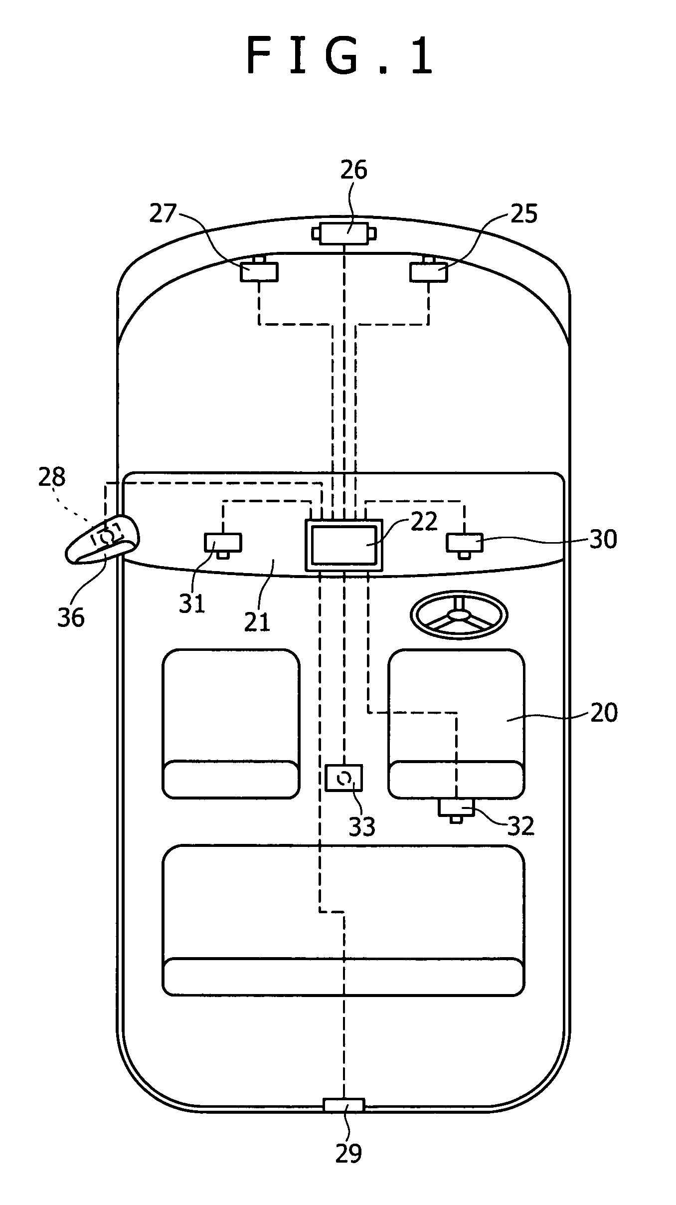
[0038]Now, the present invention will be described below referring to an embodiment shown in the figures. FIG. 1 shows the overall configuration of an automobile fitted with a camera according to this embodiment, in which a display system 22 is disposed on a substantially central portion of an instrument panel 21 on the skew front side of a driver's seat 20 of the automobile. The display system 22 is composed, for example, of a liquid crystal display panel, functions to display an image picked up by the camera, and functions also as a car navigation display system.

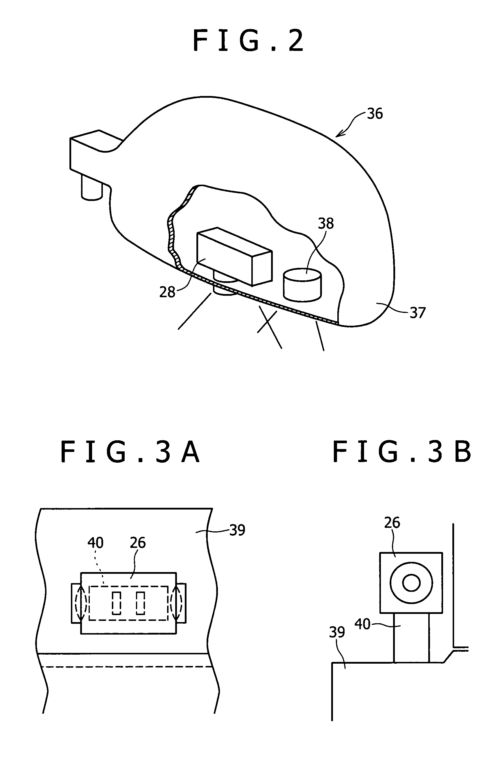
[0039]Cameras to be connected to the display system 22 include a front view camera 25, a side view camera 26, a night eye camera 27, a left side view camera 28, a rear view camera 29, a driver's seat monitor camera 30, an assistant driver's seat camera 32, a security camera 33 and the like. All the cameras 25 to 33 may not necessarily be provided, and some of them may be provided.

[0040]The front view camera 25 is a camera ...


PUM


Abstract

First to fourth lenses are aligned in an optical axis direction by a lens-barrel of a camera, an O-ring is disposed between the first lens and the lens-barrel, an O-ring is disposed between the fourth lens and the lens-barrel, a space is formed between the first and second lenses, a space is formed between the second and fourth lenses, a space is formed between the third and fourth lenses, and flow of air between the spaces is precluded. The camera thus configured is free of dewing on the lens or a protective plate exposed to the exterior, even when the inside temperature is raised due to heat generation in a CCD or a mounting substrate on which the CCD is mounted.

Description

[0001]The present application claims priority to Japanese Patent Application(s) JP2004-078216, filed in the Japanese Patent Office Mar. 18, 2004, the entire contents of which is incorporated herein by reference.BACKGROUND OF THE INVENTION[0002]The present invention relates to a camera, particularly to a camera including an optical system for condensing picture rays onto a light-receiving surface of a solid state image pickup device (CCD) to thereby perform imaging.[0003]CCD cameras using solid state image pickup devices, for example, those disclosed in Japanese Patent Nos. 3277974 and 3297946 have been widely used. Generally, a CCD type solid state image pickup device has a configuration in which light receiving devices for constituting pixels are arranged in a matrix, signals obtained by photo-electric conversion at each light receiving device are read out to a vertical register provided in correspondence with each vertical column of the light receiving devices, the signals are tra...

Claims


Application Information

Patent Timeline
Patent Type & Authority Patents(United States)
IPC IPC(8): H04N5/225G03B17/02G02B7/02B60R1/00B60R1/06B60R1/12B60R11/04G03B17/08
CPCB60R1/00H04N5/2254B60R2001/1253B60R2300/103B60R2300/105B60R2300/106B60R2300/207B60R2300/8013B60R2300/802B60R2300/8053B60R2300/8066B60R2300/8073H04N23/55
Inventor IWASAKI, KEIICHIYAMAGUCHI, YUKIMASANAKAGAWA, KIYOSHI
Owner SONY CORP
Why Eureka
Try Eureka