Lock mechanism for stage apparatus
a technology for locking mechanisms and stage equipment, which is applied in the direction of connection contact material, television system, instruments, etc., can solve the problems of inability to lock the movable stage, the size of the driving device of the locking mechanism needs to be increased, and the size of the lock mechanism and the stage apparatus is undesirable, so as to achieve the effect of simple structur
- Summary
- Abstract
- Description
- Claims
- Application Information
AI Technical Summary
Benefits of technology
Problems solved by technology
Method used
Image
Examples
first embodiment
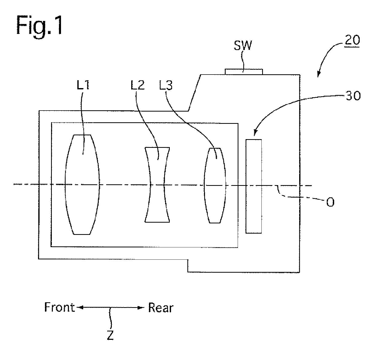
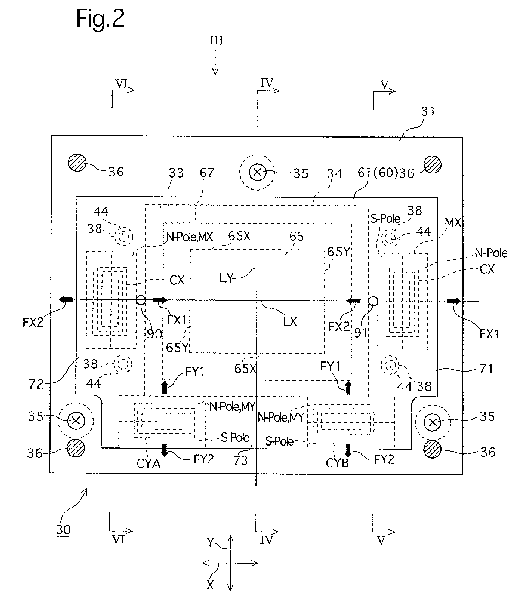
[0071]the present invention will be described hereinafter with reference to FIGS. 1 through 12. In the following description, as shown by the arrows in FIGS. 1 and 2, the left / right direction, the upward / downward direction, and the forward / rearward direction of a camera-shake correction apparatus (hand-shake correction apparatus / stage apparatus) 30 is defined as the X-direction, the Y-direction and the Z-direction, respectively.
[0072]Firstly the camera-shake correction apparatus 30, which has a lock mechanism 100 of the present invention installed therein, will be described.
[0073]As shown in FIG. 1, an optical system having first, second and third lens groups L1, L2 and L3, is provided in a digital camera 20, and the camera-shake correction apparatus 30 is provided behind the third lens group L3.
[0074]The camera-shake correction apparatus 30 has a construction as shown in FIGS. 2 through 6. As shown in FIGS. 2 through 6, the camera-shake correction apparatus 30 is provided with a f...
second embodiment
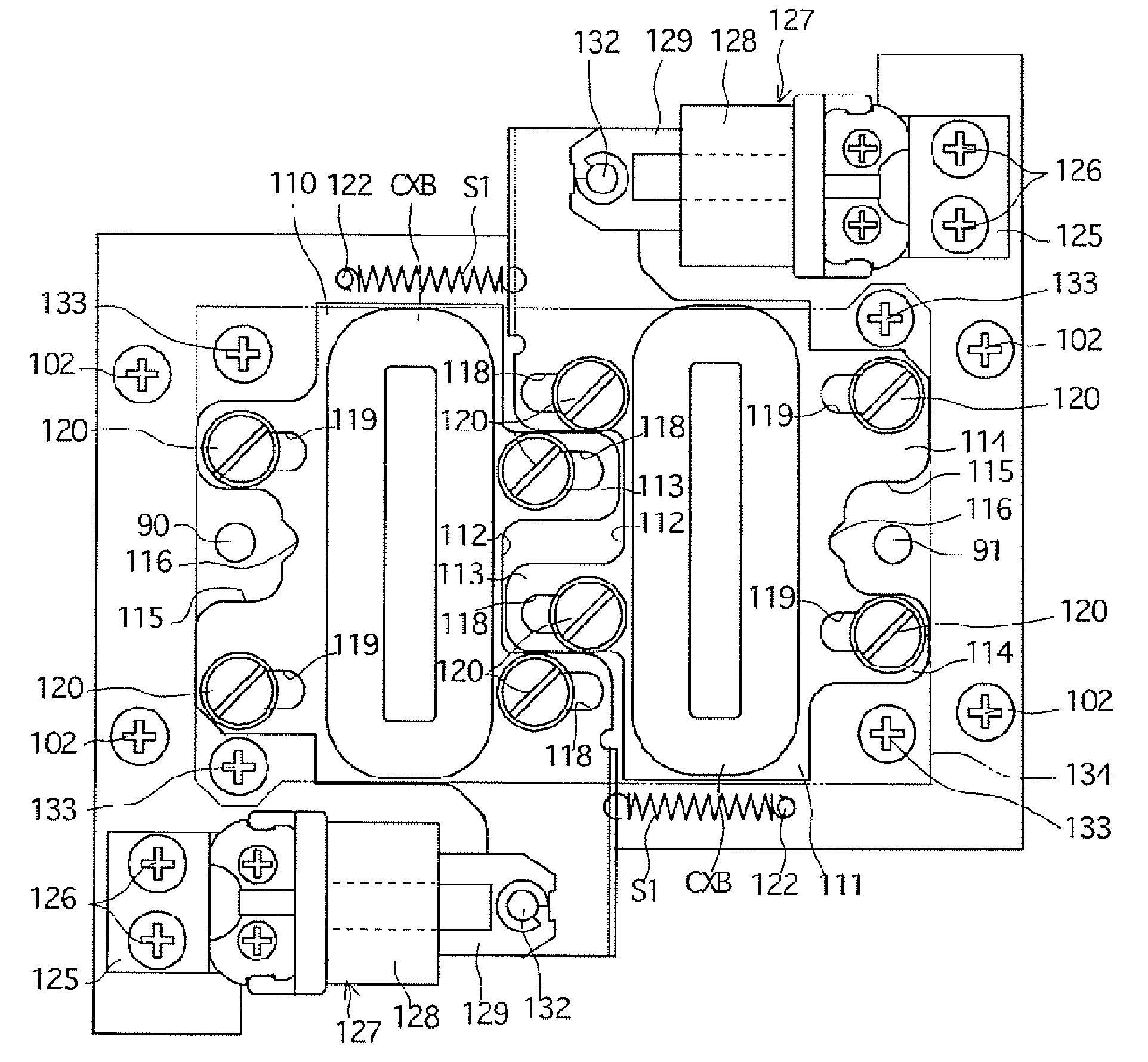
[0138]According to the above description of the second embodiment, the engaging pins 90 and 91 of the movable stage 62, which is positioned at the initial position, can be securely locked by using the lock-engaging groove 218 of the left lock member 210 and the lock-engaging groove 238 of the lock-engaging member 237.
[0139]Furthermore, since the left and right lock members 210 and 211, and the lock-engaging member 237 are all provided in between (inner sides of) the engaging pins 90 and 91, it is possible to reduce the horizontal width (in the left / right direction) of the lock mechanism 200 compared to the case where the engaging pins 90 and 91 were to be engaged with the lock-engaging grooves 218 and 238 from the outer sides of the engaging pins 90 and 91.
[0140]Since the movement of the left and right lock members 210 and 211 are interlinked by a link mechanism (link member 231), only one extension spring S2 and one plunger 127 are necessary, so that the number of members of the lo...
fourth embodiment
[0170]A front yoke 601 of the lock mechanism 600 is made from a magnetic material such as soft iron and has a general shape which substantially the same as that of the front yoke 401 of the The front yoke 601 is provided with four square holes 205 which are formed in the vicinity of four corners of the front yoke 601. Furthermore, the rear stationary support board 32 is provided with four insertion holes (square through-holes) 92 which correspond to the four square holes 205 and have the size and shape as the four square holes 205, respectively. A left side portion of the rear surface of the movable stage 62 (rear surface of the reinforcing plate 61) is provided with a pair of upper and lower engaging pins 90, and a right side portion of the rear surface of the movable stage 62 (rear surface of the reinforcing plate 61) is provided with a pair of upper and lower engaging pins 91. The upper and lower engaging pins 90 extend through the upper and lower left insertion holes 92 and the...
PUM
 Abstract
Description
Claims
Application Information
 - R&D
- Intellectual Property
- Life Sciences
- Materials
- Tech Scout
- Unparalleled Data Quality
- Higher Quality Content
- 60% Fewer Hallucinations
Browse by: Latest US Patents, China's latest patents, Technical Efficacy Thesaurus, Application Domain, Technology Topic, Popular Technical Reports.
© 2025 PatSnap. All rights reserved.Legal|Privacy policy|Modern Slavery Act Transparency Statement|Sitemap|About US| Contact US: help@patsnap.com


