Apparatus and method for determining the temperature of a charging power source

a technology of charging power source and apparatus, which is applied in the direction of instruments, greenhouse gas reduction, heat measurement, etc., can solve the problems of lead-acid batteries and other types of batteries, poor recharging control of conventional chargers, and depletion of power of lead-acid batteries

Inactive Publication Date: 2010-03-02
SPX CORP
View PDF33 Cites 7 Cited by
  • Summary
  • Abstract
  • Description
  • Claims
  • Application Information

AI Technical Summary

Benefits of technology

[0010]It is therefore a feature and advantage of the present invention to provide a method and apparatus for detecting and sensing the temperature of a battery while it is being charged and / or tested.
[0011]In another aspect of the present invention, a method and apparatus is provided for using the temperature data to adjust the level of voltage and / or current that is applied to the battery.
[0012]The above and other features and advantages are achieved through the use of a novel automatic sensor strategically placed to monitor the temperature of a charging battery as herein disclosed. In accordance with one embodiment, an apparatus is provided which includes a battery charger, a microprocessor linked to the battery charger and an automatic temperature sensor linked to the microprocessor. The apparatus can also include a battery tester to initially test the battery and its functionality as well as the battery's ability to maintain a charge.
[0013]In another aspect of the invention, the temperature sensor is linked to a microprocessor. The data from the temperature is analyzed to determine if the battery is maintaining a charge. From analyzing the temperature, the load applied to the battery can be adjusted.
[0014]In accordance with another aspect of the present invention, a method is provided for monitoring the temperature of a battery that is either being charged or tested. The method includes applying a load to a rechargeable battery, automatically monitoring a temperature of the battery in response to the load and transmitting the temperature to a microprocessor. Further steps are analyzing the temperature of the battery and comparing the temperature to a reference point. Analyzing the temperature is accomplished through an understanding of the battery type and its related charging and testing information. If the temperature exceeds the reference battery temperature, the device ceases further charging of the battery until such time when the temperature has reached a certain operating level. Once it has approximately reached this level, the load is reapplied to the battery. The temperature is measured with an infrared device and transmitted internally or externally (e.g. remotely or wireless) to a location where it is analyzed.
[0015]In accordance with another aspect of the invention, an apparatus is provided for monitoring the temperature of a battery during charging or testing of a battery. The apparatus includes means for applying a load to a rechargeable battery, means for automatically monitoring a temperature of the battery in response to the load and means for transmitting the temperature to a microprocessor. Additionally, the apparatus can include means for analyzing the temperature of the battery and means for comparing the temperature to a reference point and means for regulating the load to the battery based if the temperature of the battery exceeds the reference point.

Problems solved by technology

Because the lead-acid batteries can be depleted of power overtime, such as when they are not in use over a period of time, or when a light in a car is left on for an extended period of time, they need to be recharged and tested.
Many defects found in lead-acid batteries and other types of batteries are the result of poor recharging control in conventional chargers.
For example, an operator may undercharge or overcharge the battery at a very high rate resulting in the deterioration of the battery.
Overcharging a battery wastes energy, reduces the life of the battery, and may permanently damage the battery.
Because conventional battery requires actual visual inspection of the gauges, the operator can waste valuable time and money to inspect all the batteries that are currently being charged instead of generating money by working on other projects.

Method used


Image

  • Apparatus and method for determining the temperature of a charging power source
  • Apparatus and method for determining the temperature of a charging power source
  • Apparatus and method for determining the temperature of a charging power source

Examples


Embodiment Construction

[0025]The present invention relates a battery charger / tester with a temperature sensing device for detecting the temperature of a battery being tested and charged, as well as, detecting the temperature of the battery / charger itself.

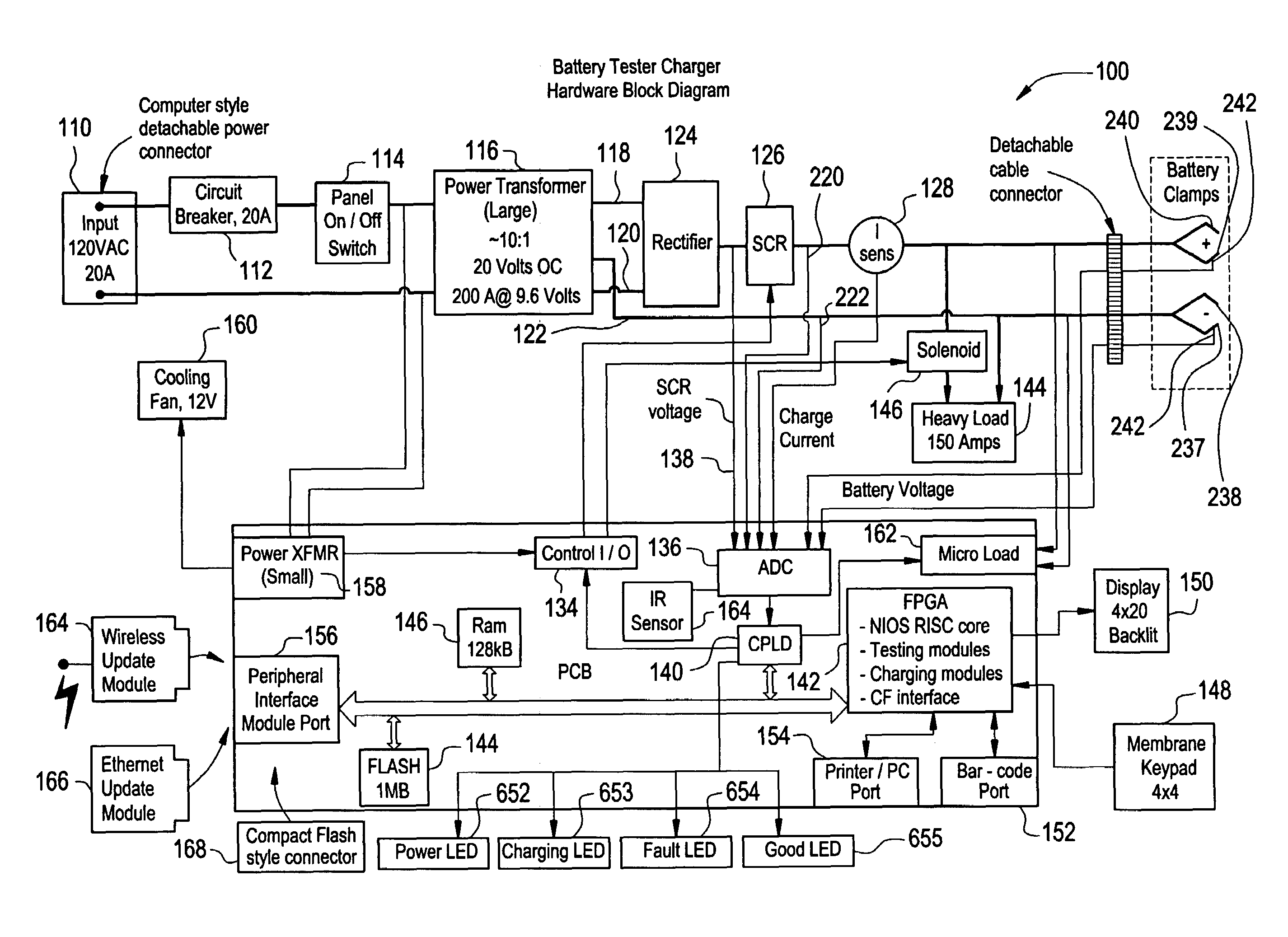
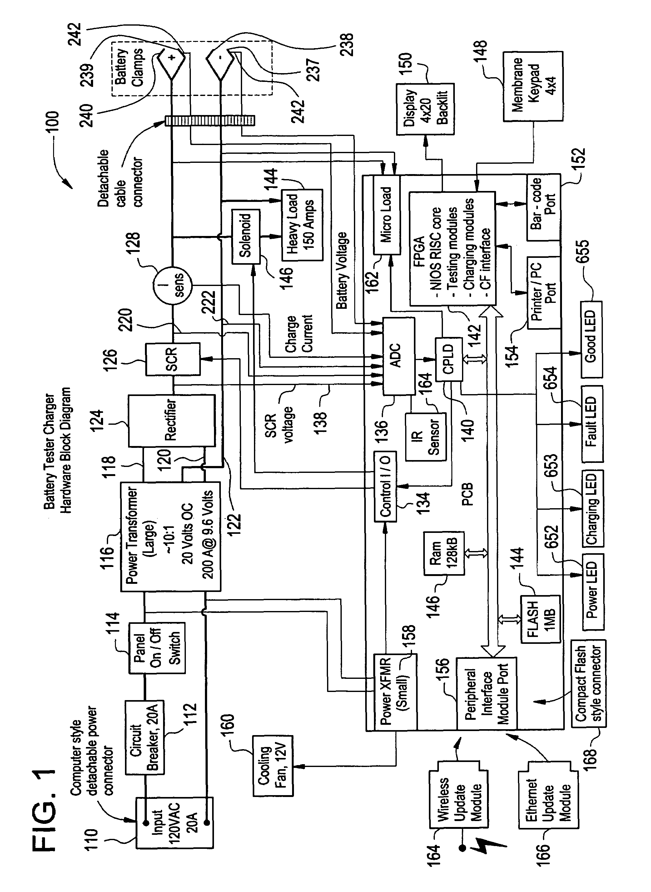
[0026]FIG. 1 is an embodiment of the current invention. The battery charger / tester 100 (“charger 100”) can include a power source 110 that provides a 120V (volts) AC (alternating current) to the charger 100. A circuit breaker 112 is provided to prevent damage that can be caused by a sudden power surge or a short in the system. A power switch 114 is linked to the power source 110 to enable the operator to turn the charger 100 on or off.

[0027]A power transformer 116 is provided to step down both the voltage and current to a level that enables the charger 100 to charge and / or test a battery. In a preferred embodiment, the power source 110 supplies the charger 100 with 120V AC. The power transformer 116 reduces the 120V AC to approximately 20-25V AC, which is...


PUM

PropertyMeasurementUnit
voltagesaaaaaaaaaa
voltagesaaaaaaaaaa
voltageaaaaaaaaaa

Abstract

A method and apparatus for automatically sensing the temperature of a battery during the testing and charging. The method and apparatus can monitor the temperature of the battery, the charger or both. Additionally, a user can be notified when the temperature is at or exceeds a predetermined level. The temperature data is also used to aid in efficiently charging the battery.

Description

[0001]Under the provisions of Section 119(e) of 35 U.S.C., Applicants hereby claim the benefit of the filing date of Prior Provisional Application No. 60 / 391,621, filed Jun. 27, 2002, for the above identified United States Patent Application.FIELD OF THE INVENTION[0002]Embodiments of the present invention generally relate to a power source charger and tester. More particularly, the present invention relates to an apparatus and method to charge and test a battery, wherein the apparatus includes a temperature sensor for detecting temperature of both a battery and the apparatus.BACKGROUND OF THE INVENTION[0003]Rechargeable batteries are an important source of clean portable power in a wide variety of electrical applications, including automobiles, boats and electric vehicles. Lead-acid batteries are one form of rechargeable battery that are commonly used to start engines, propel electric vehicles, and to act as a source of back-up power when an external supply of electricity is interru...

Claims


Application Information

Patent Timeline
Patent Type & Authority Patents(United States)
IPC IPC(8): G01R31/36H01M10/46H01M10/48H02J7/00
CPCH01M10/46H01M10/486H02J7/0091Y02E70/40Y02B40/90Y02E60/10H02J7/007194Y02B40/00Y02E60/13
Inventor RAICHLE, KURTMURPHY, JASONSONTHEIMER, PAUL
Owner SPX CORP
Why Eureka
Try Eureka