Seat back structure

a seat back and structure technology, applied in the field of seat backs, can solve the problems of difficult to cure the liquid foaming agent into a satisfied mass of foam padding in that particular closed three-dimensional part, damage or breakage of either or both of the trim cover assembly and foam padding, and deterioration of so as to achieve the effect of improving the structure of the seat back

Inactive Publication Date: 2010-03-09
TACHI S CO LTD
View PDF23 Cites 27 Cited by
  • Summary
  • Abstract
  • Description
  • Claims
  • Application Information

AI Technical Summary

Benefits of technology

[0011]In view of the above-stated drawbacks, it is a purpose of the present invention to provide an improved structure of seat back, which includes upholstery cover assembly effective for easy integral formation of both trim cover assembly and foam padding as well as for easy attachment of the upholster cover assembly itself to substantial a whole of seat back frame.

Problems solved by technology

However, with regard to the JP'992, it is quite difficult to properly reverse the trim cover assembly so that both foam pad and seat back frame are neatly covered with such reversed trim cover assembly, which may cause the possibility that both or either of the trim cover assembly and foam padding will be damaged or broken.
Further, it is technically difficult to cure the liquid foaming agent into a satisfied mass of foam padding in that particular closed three-dimensional part.
Obviously, for both of those prior arts, great difficulty has remained in terms of filling a foam padding satisfactorily in the trim cover assembly as well as of neatly attaching both of the foam padding and trim cover assembly to a seat back frame.

Method used


Image

  • Seat back structure
  • Seat back structure
  • Seat back structure

Examples


Embodiment Construction

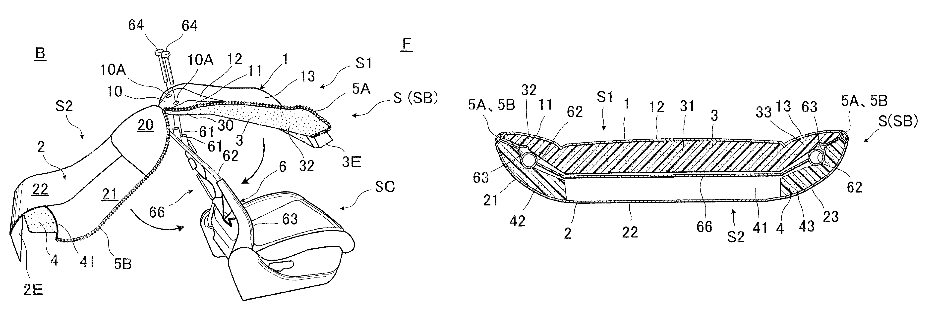
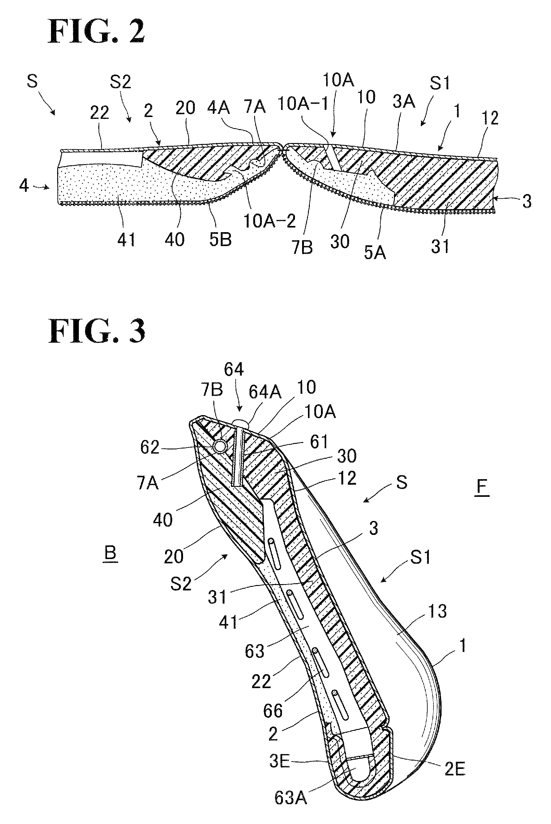
[0031]Referring to FIGS. 1 to 5, there is illustrated a preferred mode of seat back structure in accordance with the present invention.

[0032]As seen from FIGS. 1 and 4, an automotive seat is provided, which comprises: an ordinary known seat cushion (SC); and a seat back (SB) having a headrest (H) mounted on the top thereof, the seat back (SB) being of a novel characteristic structure in the present invention as will be described hereinafter.

[0033]Designation (6) in FIG. 1 represents a conventional seat back frame which is at the lower end thereof connected with the seat cushion (SC). The seat back frame (6) is composed of a generally inverted-U-shaped upper frame member (62) and a pair of vertically extending lateral frame members (63) (63).

[0034]As ordinarily know in the art, the seat back frame (6) includes resilient support elements (66), such as a plurality of sinuous springs, which are extended between those two lateral frame members (63) in order to elastically support a back ...


PUM


Abstract

Structure of seat back is provided, which comprises: a seat back frame; and an upholstery cover assembly including a forward upholster cover element and a backward upholstery cover element. Those two upholstery cover elements cover respective forward and backward sides of the seat back frame, with an upper region thereof secured on top portion of the seat back frame by a headrest stay holder element. Outer peripheral ends of those two upholstery cover elements are engaged together by an engagement element, so that substantially a whole of the seat back frame is covered with the upholstery cover assembly, thus forming a seat back.

Description

BACKGROUND OF THE INVENTION[0001]1. Field of the Invention[0002]The present invention relates to a seat back of automotive seat, and in particular to a structure of the seat back which is easy to assemble.[0003]2. Description of Prior Art[0004]As is known in the art, assembly of a seat back of automotive seat involves attaching a padding over a seat back frame to provide a basic seat back unit and then enclosing such seat back unit with a three-dimensional trim cover assembly. The three-dimensional trim cover assembly is preformed by connecting a plurality of cover materials with one another, as by sewing, so as to assume a predetermined three-dimensional configuration that substantially conforms to outer contour of the basic seat back unit.[0005]Hitherto, various attempts have been made to allow for easy covering the basic seat back unit with the foregoing three-dimensional trim cover assembly.[0006]For example, the Japanese Laid-Open Patent Publication No. 2-177992 (hereinafter, “...

Claims


Application Information

Patent Timeline
Patent Type & Authority Patents(United States)
IPC IPC(8): A47C31/02
CPCB60N2/5816B60N2/72
Inventor TAGUCHI, MASAYUKIITOU, YASUYUKI
Owner TACHI S CO LTD
Why Eureka
Try Eureka