Performance testing apparatus for heat pipes

a technology of performance testing and heat pipes, applied in the direction of lighting and heating apparatus, instruments, heat measurement, etc., can solve the problems of inability to accurately reflect the performance of the heat pipe, inability to achieve rth and qmax, and inability to achieve precise linear movement toward/away.

Inactive Publication Date: 2010-03-09
HON HAI PRECISION IND CO LTD
View PDF12 Cites 9 Cited by
  • Summary
  • Abstract
  • Description
  • Claims
  • Application Information

AI Technical Summary

Benefits of technology

[0009]What is needed, therefore, is a high performance testing apparatus for heat pipes suitable for use in mass production of heat pipes.
[0010]A performance testing apparatus for a heat pipe in accordance with a preferred embodiment of the present invention comprises an immovable portion having a cooling structure defined therein for cooling a heat pipe requiring testing. A movable portion is capable of moving relative to the immovable portion and has a cooling structure defined therein for cooling the heat pipe. A receiving structure is located between the immovable portion and the movable portion for receiving the heat pipe therein. At least a temperature sensor is attached to at least one of the immovable portion and the movable portion for thermally contacting the heat pipe in the receiving structure for detecting temperature of the heat pipe. An enclosure encloses the immovable portion and the movable portion therein, and has sidewalls thereof slidably contacting at least one of the immovable portion and the movable portion to guide the movable portion to have an accurate linear movement toward / away from the immovable portion.
[0010]A performance testing apparatus for a heat pipe in accordance with a preferred embodiment of the present invention comprises an immovable portion having a cooling structure defined therein for cooling a heat pipe requiring testing. A movable portion is capable of moving relative to the immovable portion and has a cooling structure defined therein for cooling the heat pipe. A receiving structure is located between the immovable portion and the movable portion for receiving the heat pipe therein. At least a temperature sensor is attached to at least one of the immovable portion and the movable portion for thermally contacting the heat pipe in the receiving structure for detecting temperature of the heat pipe. An enclosure encloses the immovable portion and the movable portion therein, and has sidewalls thereof slidably contacting at least one of the immovable portion and the movable portion to guide the movable portion to have an accurate linear movement toward / away from the immovable portion.

Problems solved by technology

However, Rth and Qmax can not be obtained from this test, and the performance of the heat pipe can not be reflected exactly by this test.
However, in the test, the related testing apparatus has drawbacks as follows: a) it is difficult to accurately determine lengths of the evaporating section 2a and the condensing section 2b which are important factors in determining the performance of the heat pipe 2; b) heat transference and temperature measurement may easily be affected by environmental conditions; c) it is difficult to achieve sufficiently intimate contact between the heat pipe and the heat source and between the heat pipe and the heat sink, which results in unsteady performance test results of the heat pipe.
Furthermore, due to fussy and laborious assembly and disassembly in the test, the testing apparatus can be only used in the laboratory, and can not be used in the mass production of heat pipes.
In mass production of heat pipes, a large number of performance tests are needed, and the apparatus is used frequently over a long period of time; thus, the apparatus not only requires good testing accuracy, but also requires easy and accurate assembly with the heat pipes to be tested.

Method used


Image

  • Performance testing apparatus for heat pipes
  • Performance testing apparatus for heat pipes
  • Performance testing apparatus for heat pipes

Examples


Embodiment Construction

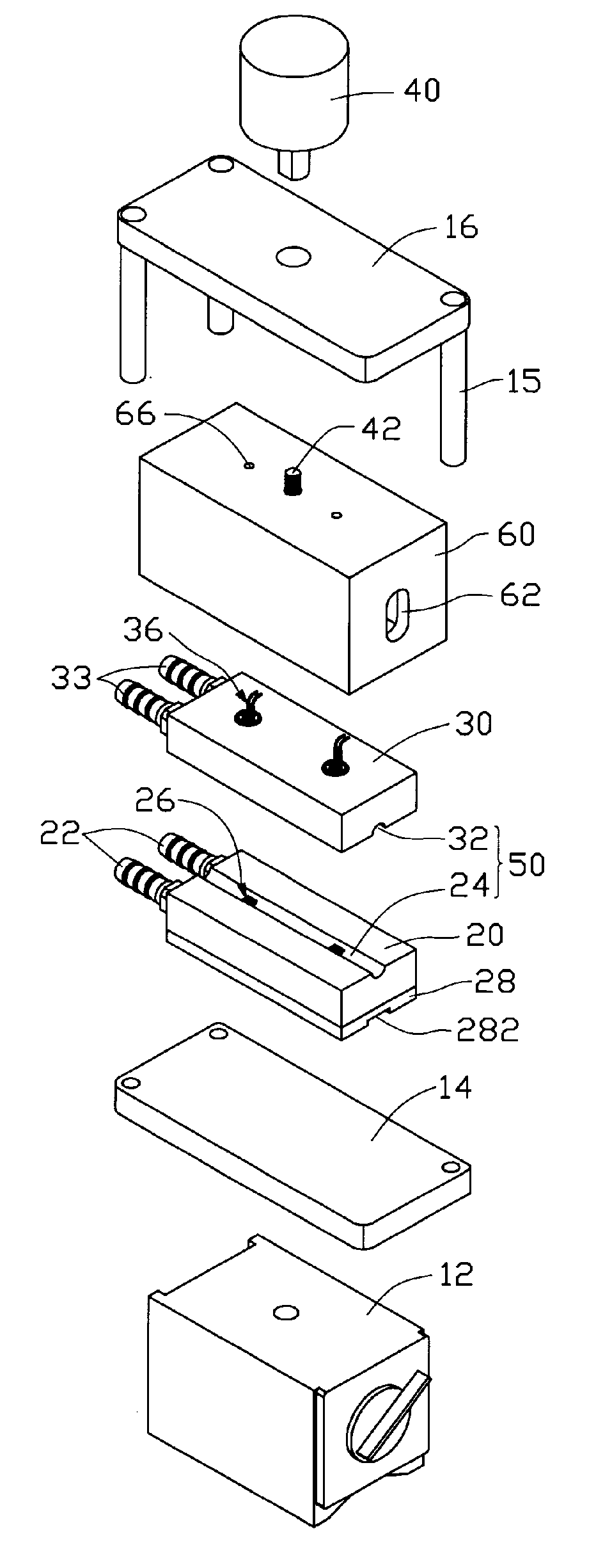
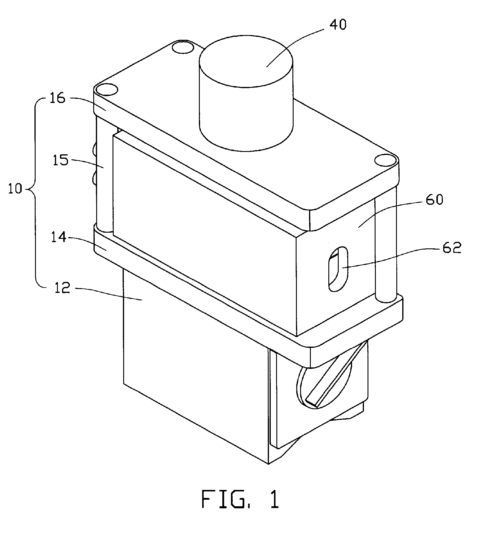
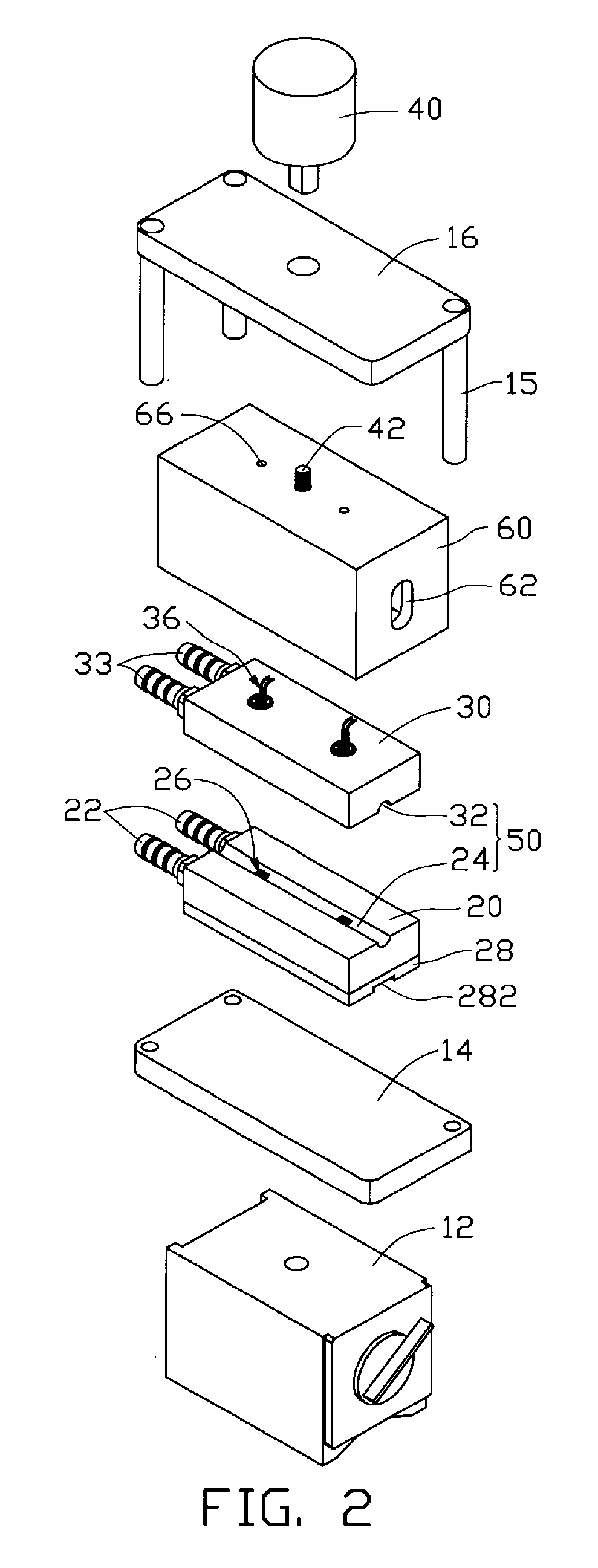
[0019]Referring to FIGS. 1-3, a performance testing apparatus for heat pipes comprises an immovable portion 20 and a movable portion 30 movably mounted on the immovable portion 20.

[0020]The immovable portion 20 is made of metal having good heat conductivity. Cooling passageways (not shown) are defined in the immovable portion 20, to allow coolant to flow therein. An inlet 22 and an outlet 22 communicate the passageways with a constant temperature coolant circulating device (not shown); therefore, the passageways, inlet 22, outlet 22 and the coolant circulating device corporately define a cooling system for the coolant circulating through the immovable portion 20 to remove heat from the heat pipe in test. The immovable portion 20 has a cooling groove 24 defined in a top face thereof, for receiving a condensing section of the heat pipe to be tested therein. Two temperature sensors 26 are inserted into the immovable portion 20 from a bottom thereof so as to position detecting portions ...


PUM

PropertyMeasurementUnit
distanceaaaaaaaaaa
structureaaaaaaaaaa
temperatureaaaaaaaaaa

Abstract

A performance testing apparatus for a heat pipe includes an immovable portion having a cooling structure defined therein for cooling a heat pipe to be tested. A movable portion is capable of moving relative to the immovable portion and has a cooling structure defined therein for cooling the heat pipe. A receiving structure is located between the immovable portion and the movable portion for receiving the heat pipe therein. At least a temperature sensor is attached to at least one of the immovable portion and the movable portion for thermally contacting the heat pipe in the receiving structure for detecting temperature of the heat pipe. An enclosure encloses the immovable portion and the movable portion therein and has sidewalls thereof slidably contacting at least one of the immovable portion and the movable portion.

Description

1. FIELD OF THE INVENTION[0001]The present invention relates generally to testing apparatuses, and more particularly to a performance testing apparatus for heat pipes.2. DESCRIPTION OF RELATED ART[0002]It is well known that a heat pipe is generally a vacuumsealed pipe. A porous wick structure is provided on an inner face of the pipe, and at least a phase changeable working media employed to carry heat is contained in the pipe. Generally, according to positions from which heat is input or output, a heat pipe has three sections, an evaporating section, a condensing section and an adiabatic section between the evaporating section and the condensing section.[0003]In use, the heat pipe transfers heat from one place to another place mainly by exchanging heat through phase change of the working media. Generally, the working media is a liquid such as alcohol or water and so on. When the working media in the evaporating section of the heat pipe is heated up, it evaporates, and a pressure dif...

Claims


Application Information

Patent Timeline
Patent Type & Authority Patents(United States)
IPC IPC(8): G01K1/16
CPCG01K1/14G01K15/00F28F2200/005
Inventor LIU, TAY-JIANTUNG, CHAO-NIENSUN, CHIH-HSIENHOU, CHUEN-SHULIN, CHENG-HUI
Owner HON HAI PRECISION IND CO LTD
Why Eureka
Try Eureka