Method and apparatus for detecting servo timing marks in a magnetic disk system

a technology of magnetic disk and timing mark, which is applied in the field of method and apparatus for detecting servo timing marks in magnetic disk systems, can solve the problems of not performing servo control, reducing the discriminating power of stm as a pattern, etc., and achieves high discriminating power and improved detection capability of stm

Inactive Publication Date: 2010-03-09
WESTERN DIGITAL TECH INC
View PDF11 Cites 6 Cited by
  • Summary
  • Abstract
  • Description
  • Claims
  • Application Information

AI Technical Summary

Benefits of technology

[0026]According to embodiments of the present invention, a magnetic disk system was able to be provided, in which possibility of false detection of falsely detecting other data as STM was decreased. Furthermore, according to the invention, a magnetic disk system was able to be provided, in which possibility of false detection of STM was able to be decreased without enlarging the area of the servo data even if frequency of the servo data was increased. Furthermore, according to the invention, a magnetic disk system was able to be provided, in which possibility of false detection of STM was able to be decreased even if the bit number of the servo sector was reduced. Still furthermore, according to the invention, a reproduction method of the servo data in such a magnetic disk system was able to be provided.

Problems solved by technology

The same problem may occur when discriminating power of STM as a pattern is reduced as a result of decreasing the bit number of the servo data.
Since the system performs servo control while recognizing a bit string detected following the STM as address information or positional information of the servo data, unless the system detects the STM at an accurate position, it can not perform the servo control.

Method used


Image

  • Method and apparatus for detecting servo timing marks in a magnetic disk system
  • Method and apparatus for detecting servo timing marks in a magnetic disk system
  • Method and apparatus for detecting servo timing marks in a magnetic disk system

Examples


Embodiment Construction

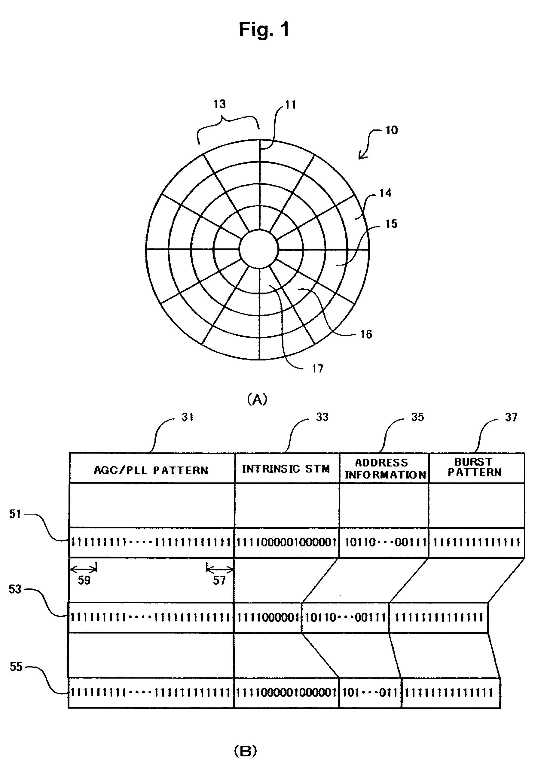
[0019]In a first aspect of embodiments in accordance with the present invention, part of an AGC / PLL pattern configures STM. Thus, possibility of false detection of recognizing other data as STM is decreased, because STM can be made into a more unique pattern with increase in bit length. On the other hand, since a storage area of a magnetic disk is reduced with increase in bit length, the bit length is restricted. Since the AGC / PLL pattern is corresponding to time inevitable for changing a mode of the magnetic disk system from recording operation of the user data to reproduction operation of the servo data, a leading portion is positioned as redundant bits. The STM is used as a reference signal for recognizing a position of the servo sector. When the STM is not recognized, recording or reproduction operation of the user data can not be performed. At that time, since the magnetic disk system is continuously operated in a reproduction mode to recognize the STM, time for switching betwe...


PUM

PropertyMeasurementUnit
frequencyaaaaaaaaaa
frequencyaaaaaaaaaa
frequencyaaaaaaaaaa

Abstract

Detection capability of a servo timing mark (STM) is improved. Long STM is configured by pseudo-STM forming part of an AGC / PLL pattern and intrinsic STM. When a system can not recognize the intrinsic STM, it keeps a state that a sector detection window is opened, and is operated in a long STM detection mode to recognize the long STM, thereby generates an STM detection signal. After the STM detection signal has been generated, an STM detection window is closed, and the system is operated in an intrinsic STM detection mode. Since the long STM has longer bit length than the intrinsic STM, it has high discriminating power with respect to other bit patterns. Therefore, even if the sector detection window is remained to be in an opened state, bit strings of data sector, address information in a servo sector or the like is not falsely recognized.

Description

CROSS-REFERENCES TO RELATED APPLICATIONS[0001]The instant nonprovisional patent application claims priority to Japanese Patent Application No.: 2005-331369, filed Nov. 16, 2005 and incorporated by reference herein for all purposes.BACKGROUND OF THE INVENTION[0002]Embodiments in accordance with the present invention relate to a technique of improving recognition capability of servo timing mark (STM) in a magnetic disk system, and furthermore relates to a technique of improving recognition capability without increasing bit length of the STM.[0003]In a magnetic disk system employing a data surface servo system (sometime called sector servo system or embedded servo system), servo sectors and data sectors are alternately arranged in a circumferential direction. When a data sector is accessed, a position of a magnetic head is controlled according to a signal reproduced from a servo sector. While the servo sector is indispensable for position control of the magnetic head in the magnetic di...

Claims


Application Information

Patent Timeline
Patent Type & Authority Patents(United States)
IPC IPC(8): G11B5/09
CPCG11B5/59688
Inventor OHZEKI, HIDEKIYOSHIDA, NOBORUISHIBASHI, KAZUYUKIUEDA, TETSUOYONEDA, ISAOWADA, TOSHIAKI
Owner WESTERN DIGITAL TECH INC
Why Eureka
Try Eureka