Method and apparatus for analysing ultrasound images

a technology of ultrasound images and methods, applied in image data processing, instruments, character and pattern recognition, etc., can solve the problems of compromising the clinical utility of images of any patient, poor resolution, and difficulty in acquiring good quality images in patients with poor acoustic windows, so as to improve the localized intensity histogram, and improve the effect of localized intensity histogram

Inactive Publication Date: 2010-03-09
RAMOT AT TEL AVIV UNIV LTD
View PDF15 Cites 11 Cited by
  • Summary
  • Abstract
  • Description
  • Claims
  • Application Information

AI Technical Summary

Problems solved by technology

The primary drawback of echocardiography is the difficulty of acquiring good quality images in patients with poor acoustic windows.
Moreover, clutter and poor resolution can compromise the clinical utility of images of any patient produced by even the most sophisticated ultrasound scanners.
With echocardiography, the difficulty of acquiring acceptable images is further compounded by the fact that the region of interest, the heart, has complex motion patterns.
However, the results obtained using the above techniques are far from being satisfactory.
In particular, echocardiograph images processed using prior art techniques suffer from poor resolution and a substantial amount of noise.
The major artifact in ultrasound images is clutter, which includes irrelevant information that appears in the imaging plane, obstructing the data of interest.
These techniques however provide less than optimal results.
Additionally, being based on adapting the data acquisition process, these techniques cannot be applied to all types of echocardiograph images.
However, with the present signal-to-noise ratio and substantial amount of clutter in echocardiograph images, visual as well as automatic determination of the LV outlines is rather difficult.
An inherent problem with automatic determination of the LV outlines is the complex motion of the Mitral Valve and the Papillary Muscles, which further increase the computational load.
An additional problem is the significant variations between different patients and different measurements of the same patient.
These attempts, however, had only limited success in border detection.
For example, prior art fail to accurately detected contours outlining the outer boundaries of the LV.

Method used


Image

  • Method and apparatus for analysing ultrasound images
  • Method and apparatus for analysing ultrasound images
  • Method and apparatus for analysing ultrasound images

Examples


example 1

Adaptive Transformation of Intensity Histogram

[0189]The teachings of the present embodiments were employed for performing adaptive transformation of intensity histograms. As further demonstrated below, the application of the teachings of the present embodiments significantly improves the quality of the Echocardiograph images.

Materials and Methods

Theoretical Background

[0190]The processing of the images was based on the fitting of the gray-level histogram curve to a sum of three Gaussians, G1, G2 and G3, representing different regions in the image. G1 represented the left ventricular cavity (low intensity Gaussian), G2 represented low-intensity pixels within the cardiac muscle (medium intensity Gaussian), and G3 represented high-intensity pixels within the cardiac muscle (high intensity Gaussian).

[0191]FIG. 5 shows a gray-level histogram of a cine-loop, referred to hereinafter as case 1.1, which is fitted to three Gaussians. In FIG. 5, the solid line correspond to the original histogr...

example 2

Clutter Detection

[0235]The teachings of the present embodiments were employed for detecting clutter in echocardiograph images. As further demonstrated below, the application of the teachings of the present embodiments allows the determination of a substantial amount of the clutter pixels, with relatively low false detection.

Materials and Methods

[0236]Theoretical Background

[0237]The clutter determination procedure was based on the fact that the cardiac wall motion is much faster than the motion of the surrounding tissue. During a single cardiac cycle, the organs primarily contributing to the clutter can be perceived as standing still with respect to the transducer. Hence, according to a preferred embodiment of the present invention stationary or substantially stationary pixels, are identified as clutter pixels.

[0238]Image Processing

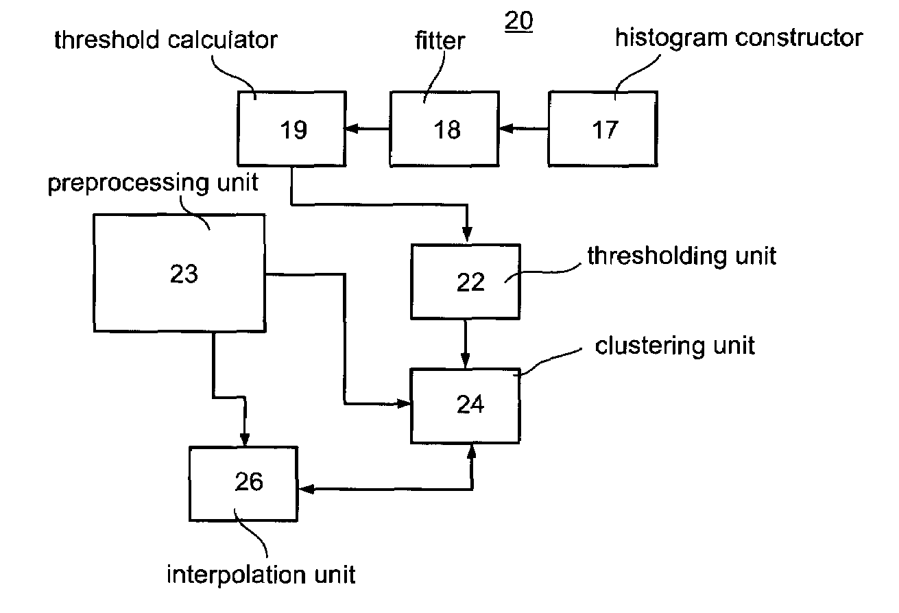
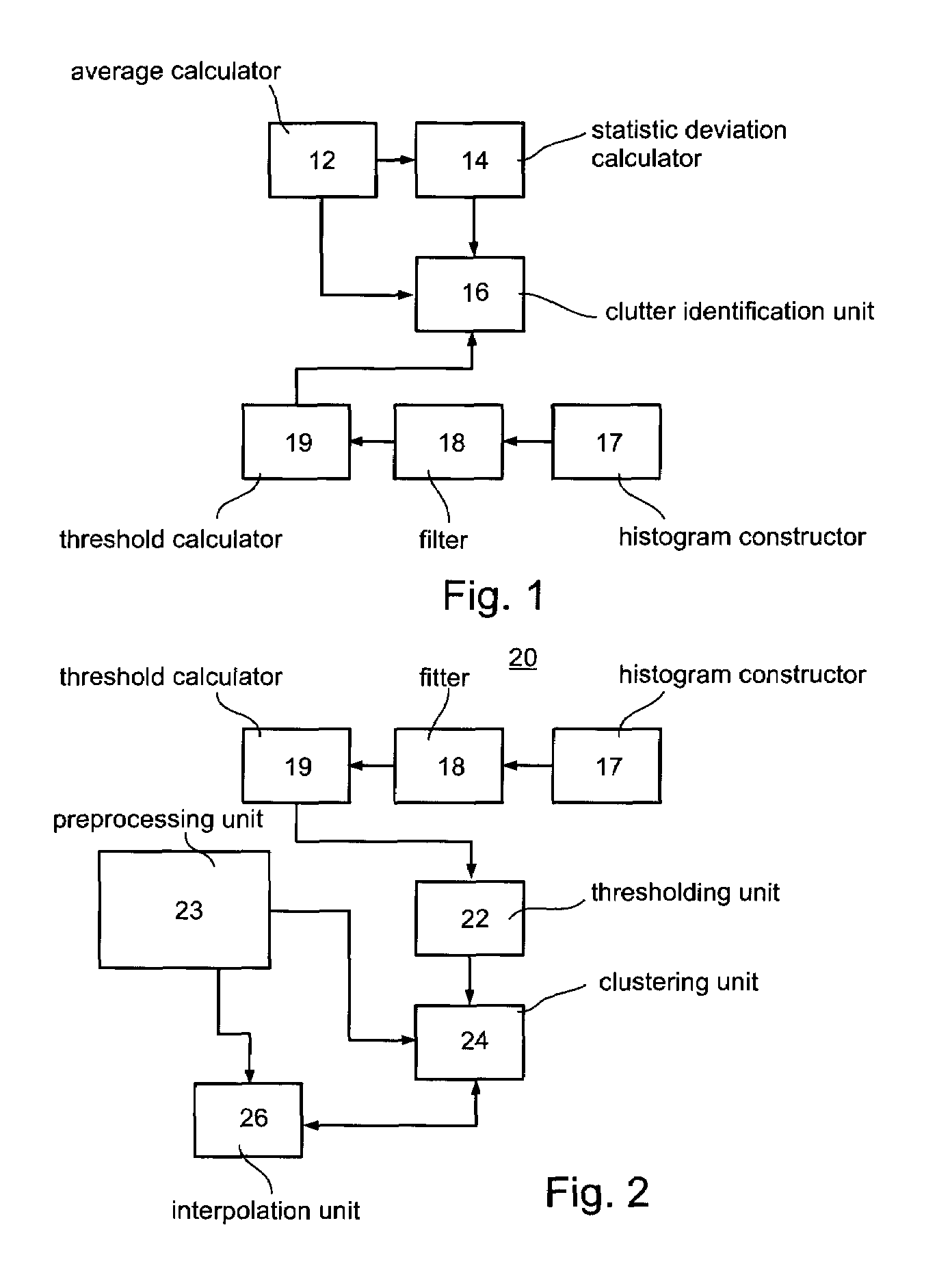
[0239]According to various exemplary embodiments of the present invention the detection of clutter can be done by executing several method steps. Referenc...

example 3

Left Ventricular Outline Detection

[0264]The teachings of the present embodiments were employed for outlining the left ventricle. As further demonstrated below, the application of the teachings of the present embodiments allows an automatic outlining of the left ventricle to a high level of accuracy.

Materials and Methods

Image Processing

[0265]According to various exemplary embodiments of the present invention, the detection of the left ventricular outlines can be done by executing several method steps. Reference is now made to FIG. 37, which is a flowchart diagram of a method of outlining a region, according to a preferred embodiment of the present invention. A description of the specific steps employed in the present example accompanies the general description of the method. As stated hereinabove, the method steps described hereinbelow can be executed either contemporaneously or sequentially in many combinations or orders of execution, and the ordering of the flowchart of FIG. 37 is ...


PUM


Abstract

A method of improving an image or a set of images, by transforming an intensity histogram thereof is disclosed. The method comprises: (a) fitting the intensity histogram to a sum of a plurality of localized functions; (b) using the plurality of localized functions to define a plurality of localized intensity histograms; (c) for each localized intensity histogram, performing at least one image enhancement procedure, thereby providing a plurality of improved localized intensity histograms; and (d) combining the plurality of improved localized intensity histograms, thereby transforming the intensity histogram of the image. In various exemplary embodiments, the method further comprises detecting clutter and / or an outline of at least one region in the image or set of images.

Description

RELATED APPLICATIONS[0001]This application is a National Phase Application of PCT Patent Application No. PCT / IL2005 / 000012 having International Filing Date of Jan. 4, 2005, which claims the benefit of U.S. Provisional Patent Application No. 60 / 534,390 filed on Jan. 7, 2004. The contents of the above Applications are all incorporated herein by reference.FIELD AND BACKGROUND OF THE INVENTION[0002]The present invention relates to image analysis and, more particularly, to methods and apparatus for analyzing and improving the quality of images obtained, e.g., during echocardiography.[0003]Imaging is recognized as the most commonly used tool in medical diagnostics. Due to its non-invasive nature, imaging is the preferred procedure prior to any invasive treatment or analysis. Medical imaging techniques include Magnetic Resonance Imaging, X-ray imaging, gamma imaging, ultrasound imaging and the like. In Magnetic Resonance Imaging, magnetic fields interact with the spins of the atoms in a ti...

Claims


Application Information

Patent Timeline
Patent Type & Authority Patents(United States)
IPC IPC(8): G06K9/18G06V30/224
CPCG06T5/40G06T5/007G06K2209/051G06T2207/10132G06T2207/30004G06V2201/031
Inventor ZWIRN, GILAKSELROD, SOLANGE
Owner RAMOT AT TEL AVIV UNIV LTD
Why Eureka
Try Eureka