Control system for a hydraulic servomotor

a control system and hydraulic servomotor technology, applied in the direction of electrical/fluid circuits, mechanical devices, couplings, etc., can solve the problems of limited e.g. pins, and is not necessarily expedient to increase the number of available electrical connections to a desired level

Inactive Publication Date: 2010-03-16
DANFOSS PAUER SOLYUSHENS APS
View PDF33 Cites 6 Cited by
  • Summary
  • Abstract
  • Description
  • Claims
  • Application Information

AI Technical Summary

Benefits of technology

[0007]It is a further object of the invention to provide a control system for a hydraulic servomotor, the control system providing the possibility of avoiding the need for an external controller for controlling the hydraulic servomotor.
[0033]The hydraulic actuator may comprise at least one additional hydraulic servomotor being arranged between diagonals of a bridge circuit. The hydraulic servomotors are preferably mechanically linked. According to this embodiment, two or more servomotors may be applied in order to obtain a desired level of output force from the system, replacing one larger servomotor providing the same level of output force. Using the smaller servomotors provides a more flexible system in the sense that the smaller servomotors may be easier fitted into the desired application than one larger servomotor.

Problems solved by technology

However, the number of available electrical connections, e.g. pins, is limited due to the size of the actuator and to strict requirements to mechanical robustness of the connector.
It is therefore not necessarily expedient to increase the number of available electrical connections to a desired level.

Method used


Image

  • Control system for a hydraulic servomotor
  • Control system for a hydraulic servomotor
  • Control system for a hydraulic servomotor

Examples


first embodiment

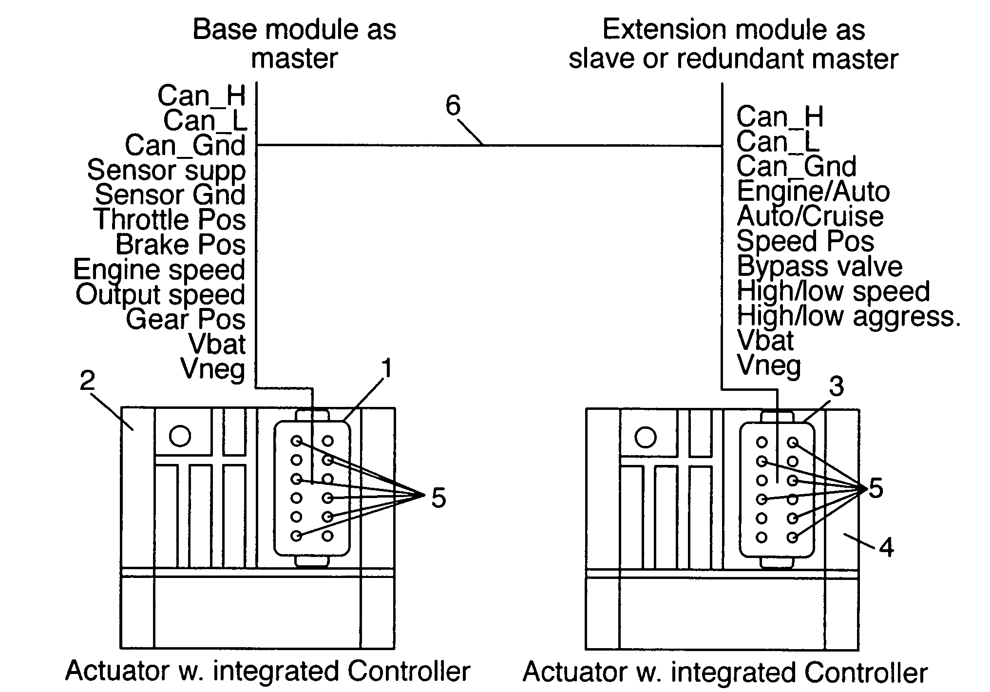
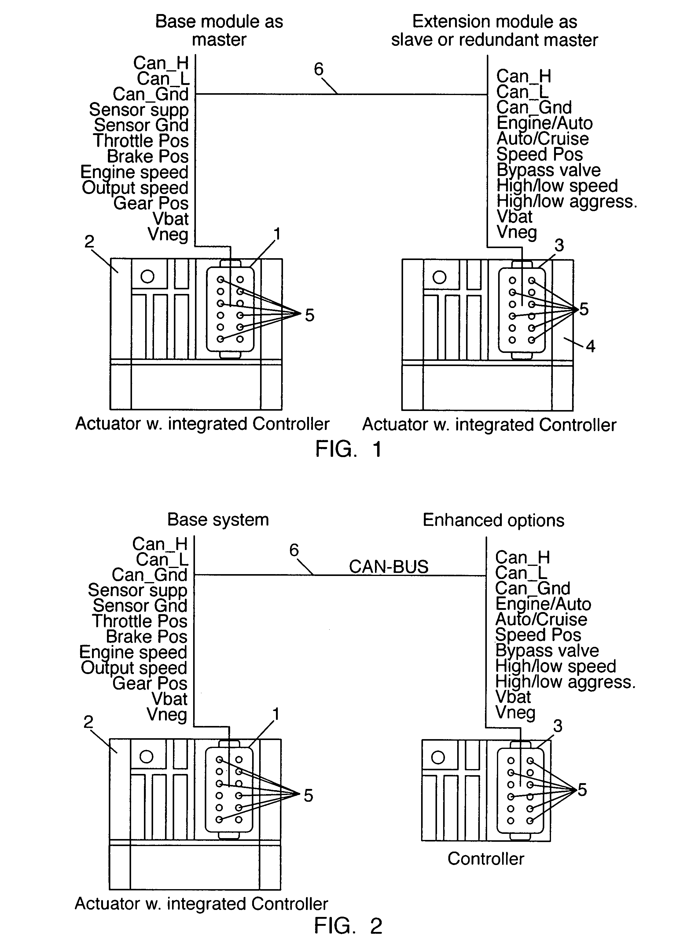
[0043]FIG. 1 illustrates a control system according to the invention. The control system of FIG. 1 comprises a main control module 1 forming part of a first electro hydraulic actuator 2. The control system further comprises an extension control module 3 forming part of a second electro hydraulic actuator 4. It is clear from FIG. 1 that the main control module 1 and the extension control module 3 are identical.

[0044]The main control module 1 and the extension control module 3 each comprises one connector having a number of connector pins 5. Via the connector pins 5 signals may be communicated to and from the control modules 1, 3, including signals communicated between the main control module 1 and the extension control module 3.

[0045]The connector pins 5 of the main control module 1 are adapted to transmit / receive signals relating to high, low and ground setting of a CanBus 6 arranged between the main control module 1 and the extension control module 3, sensor signals, throttle posit...

second embodiment

[0048]FIG. 2 illustrates a control system according to the invention. The control system illustrated in FIG. 2 is very similar to the control system illustrated in FIG. 1. However, in FIG. 2 the extension control module 3 does not form part of an electro hydraulic actuator. Thus, in this case the extension control module 3 merely provides additional connector pins 5 for the main control module 1, i.e. the extension control module 3 does not in itself control an electro hydraulic actuator.

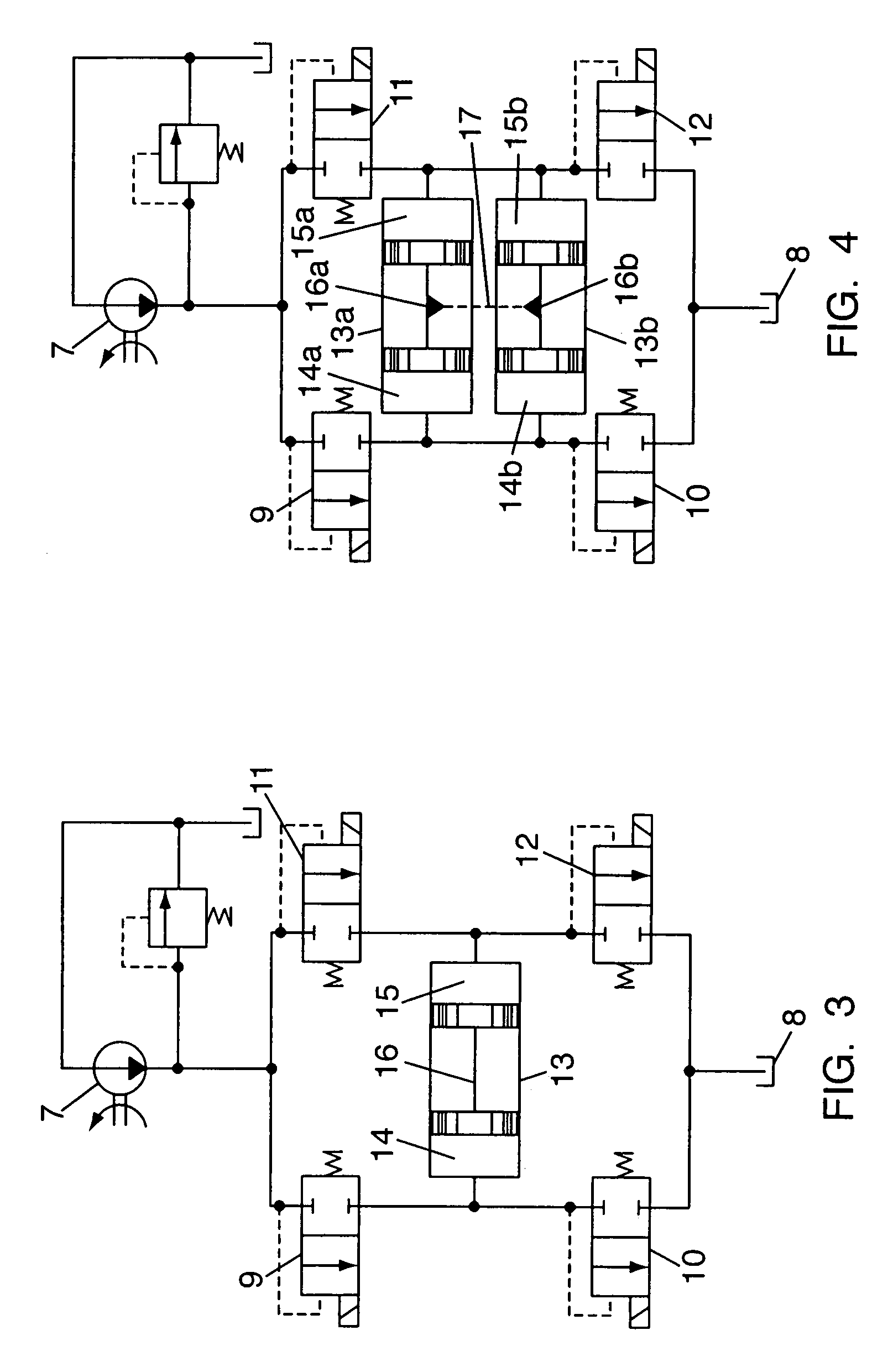
[0049]FIG. 3 is a schematic diagram illustrating a hydraulic actuator which may be applied in control systems according to the invention. The hydraulic actuator comprises a valve assembly connected between a fluid source in the form of a pump 7 and a fluid drain in the form of a tank 8. The hydraulic actuator comprises four valves 9, 10, 11, 12 arranged in a bridge circuit. A hydraulic servomotor 13 is arranged between diagonals of the bridge circuit, the hydraulic servomotor 13 defining a first cha...


PUM


Abstract

A control system for a hydraulic servomotor (13) is disclosed. The control system comprises an electro hydraulic actuator (2) comprising a number of valves (9, 10, 11, 12, 18) for controlling fluid flows, a main control module (1), and one or more connectors. The control system further comprises at least one extension control module (3) comprising one or more connectors. Finally, the control system comprises means (6) for communicating signals between the main control module (1) and each of the extension control module(s) (3). Since the main control module (1) and the extension control module(s) (3) are able to communicate signals, it is possible to provide signals to / from the main control module (1) via an extension module (3), thereby in effect providing additional connectors to the main control module (1). Thereby the main control module (1) may be able to perform additional functions as compared to similar prior art control modules.

Description

CROSS REFERENCE TO RELATED APPLICATIONS[0001]This application discloses similar subject matter as disclosed in co-pending application Ser. No. 11 / 703,431 entitled “A Hydraulic Actuator Having An Auxiliary Valve”; co-pending application Ser. No. 11 / 703,430 entitled “A Valve Assembly and A Hydraulic Actuator Comprising the Valve Assembly”; and co-pending application Ser. No. 11 / 703,314 entitled “A Hydraulic Actuator For A Servomotor With an End Lock Function” all assigned to the same Assignee and filed on the same date herewith.FIELD OF THE INVENTION[0002]The present invention relates to a control system for a hydraulic servomotor. More particularly, the present invention relates to a control system as defined above in which it is possible to allow the control system to perform additional functions as compared to similar prior art control system. Thereby it may even be possible to avoid the need for an external controller.BACKGROUND OF THE INVENTION[0003]Prior art electrical control s...

Claims


Application Information

Patent Timeline
Patent Type & Authority Patents(United States)
IPC IPC(8): F15B13/08B60R16/023
CPCF15B11/006F15B13/085F15B2211/30575F15B2211/3111F15B2211/31576F15B2211/31588F15B2211/328F15B2211/35F15B2211/351F15B2211/353F15B2211/40592F15B2211/55F15B2211/6306F15B2211/6336F15B2211/6346F15B2211/6656F15B2211/7054F15B2211/7058F15B2211/71F15B2211/7107F15B2211/8757
Inventor PLOUGSGAARD, HELGE SOEPLOUG, OLE
Owner DANFOSS PAUER SOLYUSHENS APS
Why Eureka
Try Eureka