
Tools and technology of radical and level drilling/well completion under ultra-short radius

a technology of radical and level drilling and ultra-short radius, applied in the direction of drilling pipes, directional drilling, artificial islands, etc., can solve the problems of time-consuming, difficult assembly, and difficult control of orientation, and achieve the effect of saving time and labor, convenient and convenient servi

Inactive Publication Date: 2010-03-16
BEIJING WANWEI YITONG TECHNOLOGICAL DEV
View PDF10 Cites 9 Cited by
  • Summary
  • Abstract
  • Description
  • Claims
  • Application Information

AI Technical Summary

Benefits of technology

[0003]For overcoming the technical problems mentioned above, the purpose of the invention is to introduce a new technology together with a new set of special drilling tools consisting respectively of deflecting and level drilling tools. This new technology and related new tools are featured with more accurate drilling, more convenient servicing and easier assembling. The structural members of the flexible drill pipes are fitted together with external and internal splines and matching nuts, resulting in more convenient assembling and service. What is more, drilling fluid is delivered in a way of reverse circulation in a drilling process, which avoids, effectively, “sand sticking” so as to improve working efficiency.
[0017]1. For conventional flexible drill pipes, their parts and components are fixed and connected with welding technology. In this invention a new technology for part and component fixing and connection is introduced for making flexible drill pipes—by means of splines and threading. This technology is not only time and labor saving but also easy and convenient in service.
[0018]2. Conventional directional follow-up tube is made up of trapezoidal shaped short pipe welded on a steel plate. New technology is adopted in the invention by making slotted seamless steel pipe and 50-70 mm width of tube wall left at lower part, serving as rib, which enhances intensity of parts and saves spaces.
[0019]3. For conventional technology, deflecting process is proceeded at target zone, 2-3 m of casing wall has to be cut off before utilizing whip-stock to exercise deflecting. Only a 1-1.3 m width of window in the present invention has to be cut on casing wall before deflecting operation so that reducing site work difficulty a lot and saving site work time for 2-3 days as well as less damage to casing wall and increasing its strength.
[0020]4. For conventional technology, drilling fluid is conveyed in a way of positive circulation. This invention adopts reverse circulation process for conveying drilling fluid, which has the advantages of a thorough removal of rock cuttings to ensure more accurate drilling. Since drilling fluid is delivered between the flexible drill pipe and well wall and returned to ground along holes of drill bit and the flexible drill pipe, the “sand sticking” phenomenon is avoided and work efficiency increased.

Problems solved by technology

Although R&D work on an ultra-short radius level drilling tools has gained a lot of results, there are still many technical problems.
During level interval drilling after finishing inclined interval, an orientation is difficult to be controlled, easy to cause deviation.
The earlier developed drilling tools have the shortcoming that structuring members of flexible drill pipe are fixed up or connected together by way of clasping and welding, which leads to being difficult in assembling and time-consuming in service.
Besides, drilling fluid is being delivered in a way of normal circulation in drilling process, which is easy to bring about “sand sticking” and to lower working efficiency.

Method used


Image

  • Tools and technology of radical and level drilling/well completion under ultra-short radius
  • Tools and technology of radical and level drilling/well completion under ultra-short radius
  • Tools and technology of radical and level drilling/well completion under ultra-short radius

Examples


example 1

1. Assembling of Various Tools of the Present Invention

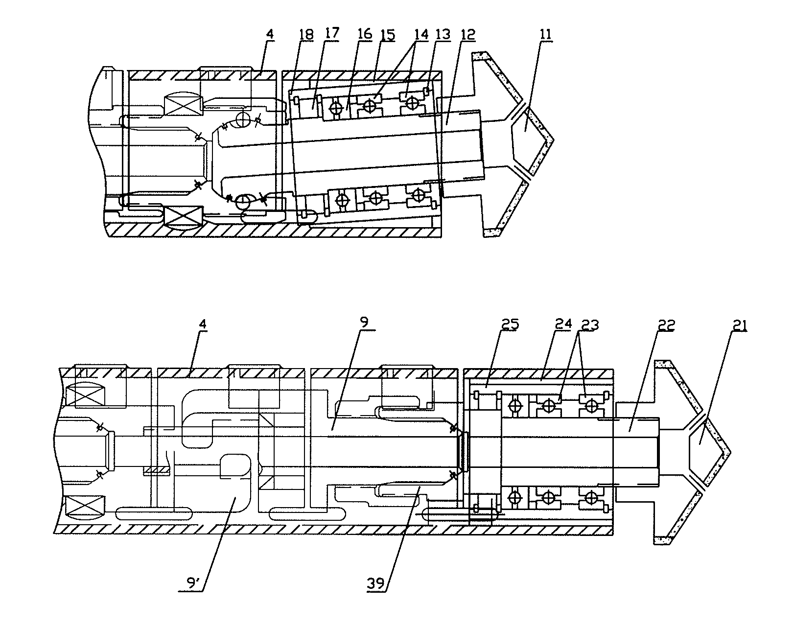
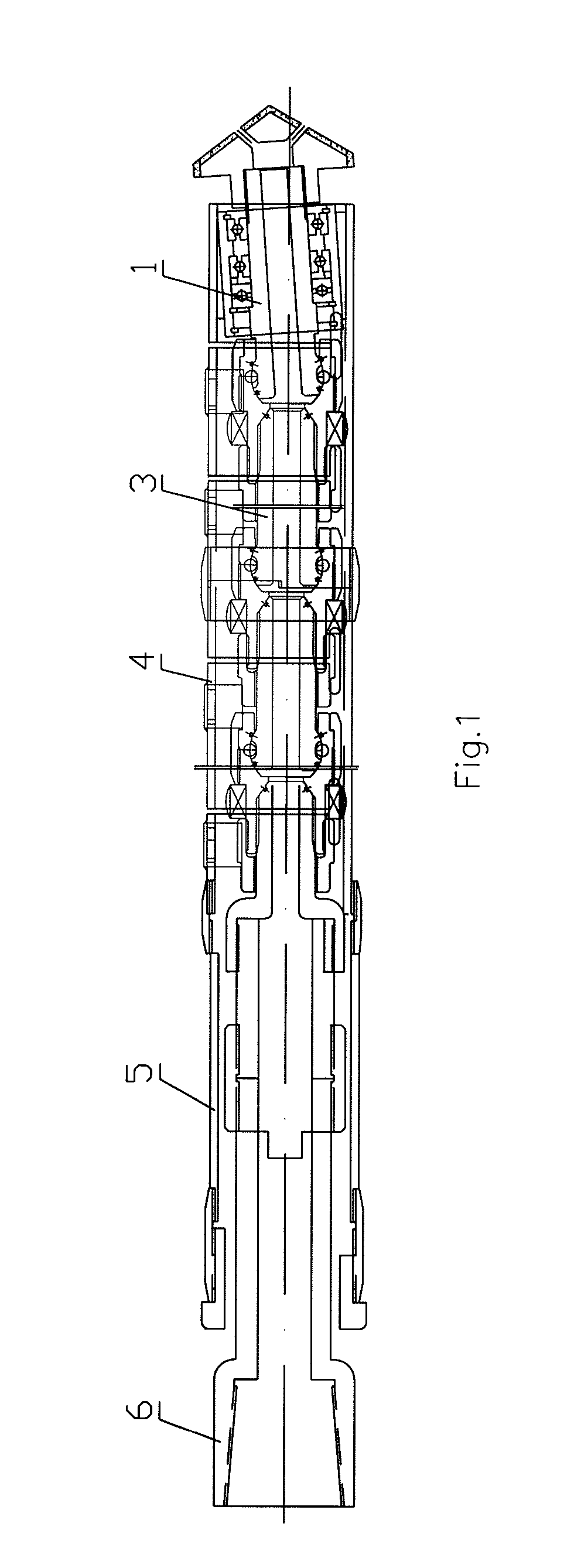
[0040](1) Fixing of the deflecting rotary assembly 1, firstly. As shown in FIG. 3, fit, one after another, the centralizing bearing 14, the pressure bearing 16, the collar 13 (for sealing), and the felt washer 17 into the casing 18 and then put them onto the central shaft 12. Connect the deflecting drill bit 11 to the front end of the central shaft 12 by way of threading, weld triangle backing block 15 onto an outer surface of the casing 18, and then weld the resulting deflecting rotary assembly 1 onto front end of the directional follow-up tube 4.

[0041](2) Fixing of the level rotary assembly 2. As shown in FIG. 4, fit, one after another, the centralizing bearing 23, the pressure bearing 16, collar 13, and the felt washer 17 into the casing 25 and then put them onto the central shaft 22. Connect the level drill bit 21 to front end of the horizontal shaft 22 by way of threading, weld rectangle cross-sectioned backing block 24 ont...

example 2

Assembling of Various Parts of the Present Invention

[0050](1) Level drilling footage is 45.0 m; length of the fixed flexible drill pipe is 45.0 m, each section of the flexible drill pipe being 150 mm long. Inner balls are made of 40# Cr—Ni—Mo.

[0051](2) The directional follow-up tube 4 is made of slotted seamless steel tube, width of slot being 4 mm and spacing between slots being 110 mm. There are 70 mm width of tube wall to be left at lower part of the tube, serving as rib.

[0052]Drilling process:

[0053]At the designed drilling depth, a 1.3 m window has to be cut on the casing wall. Bending degree of the flexible drill pipe is 18° / m and the deflecting angle is 90°. For every 5.0 m of drilling footage, the curvature radius R=5.0*4 / (2p)=3.18 m, which is within the range of ultra-short radius deflecting process all the same.

[0054]The process for making other parts and technology of drilling are described the Example 1.

example 3

Assembling of Various Parts of the Present Invention

[0055](1) Level drilling footage is 98.0 m; each section of the flexible drill pipe being 140 mm long, Length of the fixed flexible drill pipe installed is 98.0 m, Inner balls are made of 42# Cr—Mo.

[0056](2) The width of slot of the directional follow-up tube 4 is 4 mm and spacing between slots being 105 mm. There are 60 mm width of tube wall to be left at lower part of the tube, serving as a rib.

[0057]Drilling process:

[0058]Bending degree of the flexible drill pipe is 22° / m and the deflecting angle is 90°. For every 4.1 m of drilling footage, the curvature radius R=4.1*4 / (2p)=2.61 m.

[0059]The process for making other parts and technology of drilling are described in the Example 1.


PUM


Abstract

A system of components and a method is provided for radial and level drilling and completion with an ultra-short radius which includes a deflecting drill tool assembly and a level drill tool assembly. The deflecting drill tool has a deflecting rotary assembly, flexible drill pipe, directional follow-up tube, tail tube for deflecting drill tool, and drill pipe nipple joints. The level tool has a level rotary assembly, the flexible drill pipe, quick couplings, the directional follow-up tube, a tail tube for level drill tool, the drill pipe nipple joint, an adjusting nipple joint, a recessed left hand thread bushing, and convex left hand thread coupling. A triangle backing block is installed on outside of a casing of the deflecting rotary assembly. Splines matched with each other are provided at the level rotary assembly and the flexible drill pipe. The tail tube for level drill tool has a recessed left hand thread bushing and convex left hand thread coupling. A body of an inner ball is situated in a ball bowl and in frontal part of the main body of the flexible drill pipe and any single section of the flexible drill pipe may bend 3°-6°.

Description

FIELD OF THE INVENTION[0001]The invention relates to a field of extracting petroleum, particularly to a special drilling tool and oil extraction technology; namely, an apparatus and method for radial and level drilling and completion with an ultra-short radius.BACKGROUND OF THE INVENTION[0002]Although R&D work on an ultra-short radius level drilling tools has gained a lot of results, there are still many technical problems. In drilling work for inclined interval and level interval, same kind of drilling tools are being used at present. During level interval drilling after finishing inclined interval, an orientation is difficult to be controlled, easy to cause deviation. The earlier developed drilling tools have the shortcoming that structuring members of flexible drill pipe are fixed up or connected together by way of clasping and welding, which leads to being difficult in assembling and time-consuming in service. Besides, drilling fluid is being delivered in a way of normal circula...

Claims


Application Information

Patent Timeline
Patent Type & Authority Patents(United States)
IPC IPC(8): E21B7/08
CPCE21B7/06E21B17/20
Inventor CAO, XIZHANG, CAOCUNZHANG, CAOXU
Owner BEIJING WANWEI YITONG TECHNOLOGICAL DEV
Learn More