
Light emitting device having various color temperature

a technology of light-emitting devices and color temperature, which is applied in the direction of lighting and heating apparatus, discharge tube luminescnet screens, therapy, etc., can solve the problems of narrow color temperature range, low color rendering index, and chronic fatigu

Active Publication Date: 2010-03-16
SEOUL SEMICONDUCTOR
View PDF2 Cites 176 Cited by
  • Summary
  • Abstract
  • Description
  • Claims
  • Application Information

AI Technical Summary

Benefits of technology

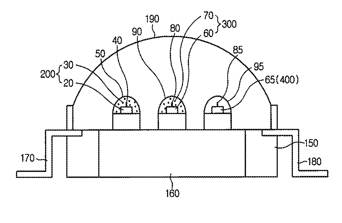
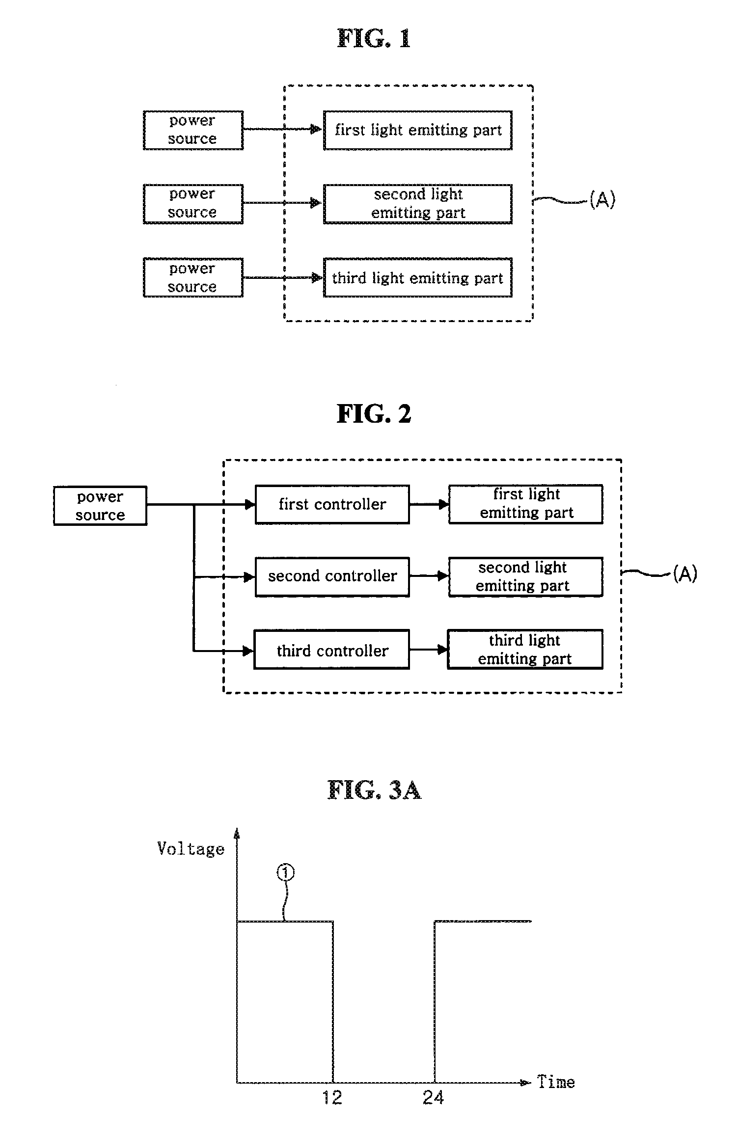
The present invention is a light emitting device that includes a plurality of light emitting parts in a single package to realize white light of various spectra and color temperatures. The device includes a first light emitting part, a second light emitting part, and a third light emitting part. The first part emits a daylight color with a high color temperature, the second part emits white light with a low color temperature, and the third part emits light in a visible range of 580 nm or more. The second and third parts are operable independently of the first part and can realize a warm white color with a low color temperature. The device is designed to accommodate the circadian rhythm of humans and provide various feelings and great influences on the physiological rhythms of humans. The invention solves the problems of conventional techniques by providing a light emitting device that can provide various spectra and color temperatures, and adjust its spectrum and color temperature based on the physiological rhythms of humans.

Problems solved by technology

As such, light provides various feelings and great influences on the physiological rhythms depending on the wavelengths and color temperature thereof, while causing various disorders, such as impaired digestion, chronic fatigue, and the like, in the case of failing to properly accommodate to variation of the light.
However, when the light emitting devices employs such phosphors, there are disadvantages of a narrow range in color temperature, a very low color rendering index, and instability of a lamp.
In other words, it is difficult to manufacture a light emitting device capable of providing various spectra or color temperatures.
Furthermore, since red-based phosphors have a lower photo efficiency, it is necessary to increase power and the amount of phosphors in order to realize white light having a lower color temperature with a blue or ultraviolet-LED chip and the phosphors.

Method used


Image

  • Light emitting device having various color temperature
  • Light emitting device having various color temperature
  • Light emitting device having various color temperature

Examples


example 1

[0083]A first light emitting part is constituted with an LED chip emitting blue light of 456 nm, Cu0.15Ba1.82Sr0.03Si0.99Ge0.01O4:Eu phosphor having a light emission peak of 515 nm, and Cu0.05Sr1.72Ca0.23Si0.99Ge0.01O4:Eu phosphor having a light emission peak of 593 nm.

[0084]A second light emitting part is constituted with an LED chip emitting blue light of 456 nm, Cu0.05Ba1.84Sr0.01Si0.99Zr0.01O4:Eu phosphor having a light emission peak of 508 nm, and Cu0.05Sr1.85Ca0.10SiO4:Eu phosphor having a light emission peak of 605 nm. Additionally, a third light emitting part is constituted with an LED chip emitting light in a visible range of 580 nm or more.

[0085]FIG. 5 is a diagram showing an emission spectrum of the first light emitting part, and FIG. 6 is a diagram showing an emission spectrum of the second light emitting part. As can be seen from these figures, the first light emitting part exhibits a higher intensity of light in the blue emitting region, and the second light emitting p...

example 2

[0088]A first light emitting part is constituted with an LED chip emitting blue light of 456 nm, Cu0.15Ba1.82Sr0.03Si0.99Ge0.01O4:Eu phosphor having a light emission peak of 515 nm, and Cu0.05Sr1.8Ca0.15SiO4:Eu phosphor having a light emission peak of 600 nm.

[0089]A second light emitting part is constituted with an LED chip emitting blue light of 456 nm, Cu0.15Ba1.82Sr0.03Si0.99Ge0.01O4:Eu phosphor having a light emission peak of 515 nm, and Cu0.05Sr1.8Ca0.15SiO4:Eu phosphor having a light emission peak of 600 nm. Additionally, a third light emitting part is constituted with an LED chip emitting light in the visible range of 580 nm or more.

[0090]In this embodiment, the first and second light emitting parts can realizes white light having different color temperatures and color rendering properties with two phosphors of different composition.

[0091]FIG. 7 is a diagram showing an emission spectrum of the first light emitting part, and FIG. 8 is a diagram showing an emission spectrum of ...

example 3

[0094]A first light emitting part is constituted with an LED chip emitting UV light of 405 nm, Cu0.02Ba2.8Sr0.2Mg0.98Si2O8:Eu phosphor having a light emission peak of 440 nm, Cu0.15Ba1.84Sr0.01Si0.99Zr0.01O4:Eu phosphor having a light emission peak of 508 nm, Cu0.02Ba0.98Sr0.98Ca0.02SiO4:Eu phosphor having a light emission peak of 565 nm, and Cu0.15Mg0.85BaP2O7:Eu, Mn phosphor having a light emission peak of 630 nm.

[0095]A second light emitting part is constituted with an LED chip emitting UV light of 405 nm, Cu0.02Ba2.8Sr0.2Mg0.98Si2O8:Eu phosphor having a light emission peak of 440 nm, Cu0.15Ba0.82Sr0.03Si0.99Ge0.01O4:Eu phosphor having a light emission peak of 515 nm, Cu0.05Sr1.72Ca0.23Si0.99Ge0.01O4:Eu phosphor having a light emission peak of 593 nm, Cu0.15Mg0.85BaP2O7:Eu, Mn phosphor having a light emission peak of 630 nm. Additionally, a third light emitting part is constituted with an LED chip emitting light in the visible range of 580 nm or more.

[0096]FIG. 9 is a diagram sho...


PUM


Abstract

A light emitting device capable of emitting light having various color temperatures is disclosed. The light emitting device includes a first light emitting part emitting a daylight color having a color temperature of 6000 K or more, a second light emitting part emitting white light having a color temperature less than 6000 K, and a third light emitting part emitting light in a visible range of 580 nm or more. The second and third light emitting parts are operable independently of the first light emitting part, and realize a warm white color having a color temperature of 3000 K or less with the white light emitted from the second light emitting part and the light emitted from the third light emitting part. The light emitting device realizes white light of various spectra and color temperatures corresponding to desired mood and utility. The light emitting device is controlled to emit light having a suitable wavelength or a suitable color temperature depending on the circadian rhythm of human, thereby enabling improvement of the user's health.

Description

CROSS-REFERENCE TO RELATED APPLICATION[0001]This application claims priority to Korean Patent Application No. 10-2007-0026750, filed Mar. 19, 2007, the contents of which are incorporated herein by reference in their entirety.FIELD OF THE INVENTION[0002]The present invention relates to a light emitting device, and more particularly to a light emitting device that includes a plurality of light emitting parts in a single package to realize a variety of spectra and color temperatures.BACKGROUND OF THE INVENTION[0003]Light Emitting Diodes (LEDs) refer to a semiconductor diode that emits light via generation and recombination of carriers, i.e. electrons and holes, in P-N junctions of a compound semiconductor. The LED consumes less power and has several to several dozen times the lifespan of conventional light bulbs or fluorescent lights, thereby being highly advantageous in terms of power reduction and durability. Additionally, the LED can be placed in a narrow space and is resistant to v...

Claims


Application Information

Patent Timeline
Patent Type & Authority Patents(United States)
IPC IPC(8): H01L33/00H01L33/50H01L33/56H01L33/60H01L33/62
CPCA61N5/0618H05B33/0857H05B33/0821H05B33/0842F21K9/00A61N2005/0652A61N2005/0662F21Y2101/02F21Y2115/10H05B45/00H05B45/20H05B45/40
Inventor KIM, DO HYUNGCHOI, HYUCK JUNG
Owner SEOUL SEMICONDUCTOR
Learn More