

Adjustable/non-adjustable precision optical mounts
- Summary
- Abstract
- Description
- Claims
- Application Information
AI Technical Summary
Benefits of technology
Problems solved by technology
Method used
Image

Examples
first embodiment
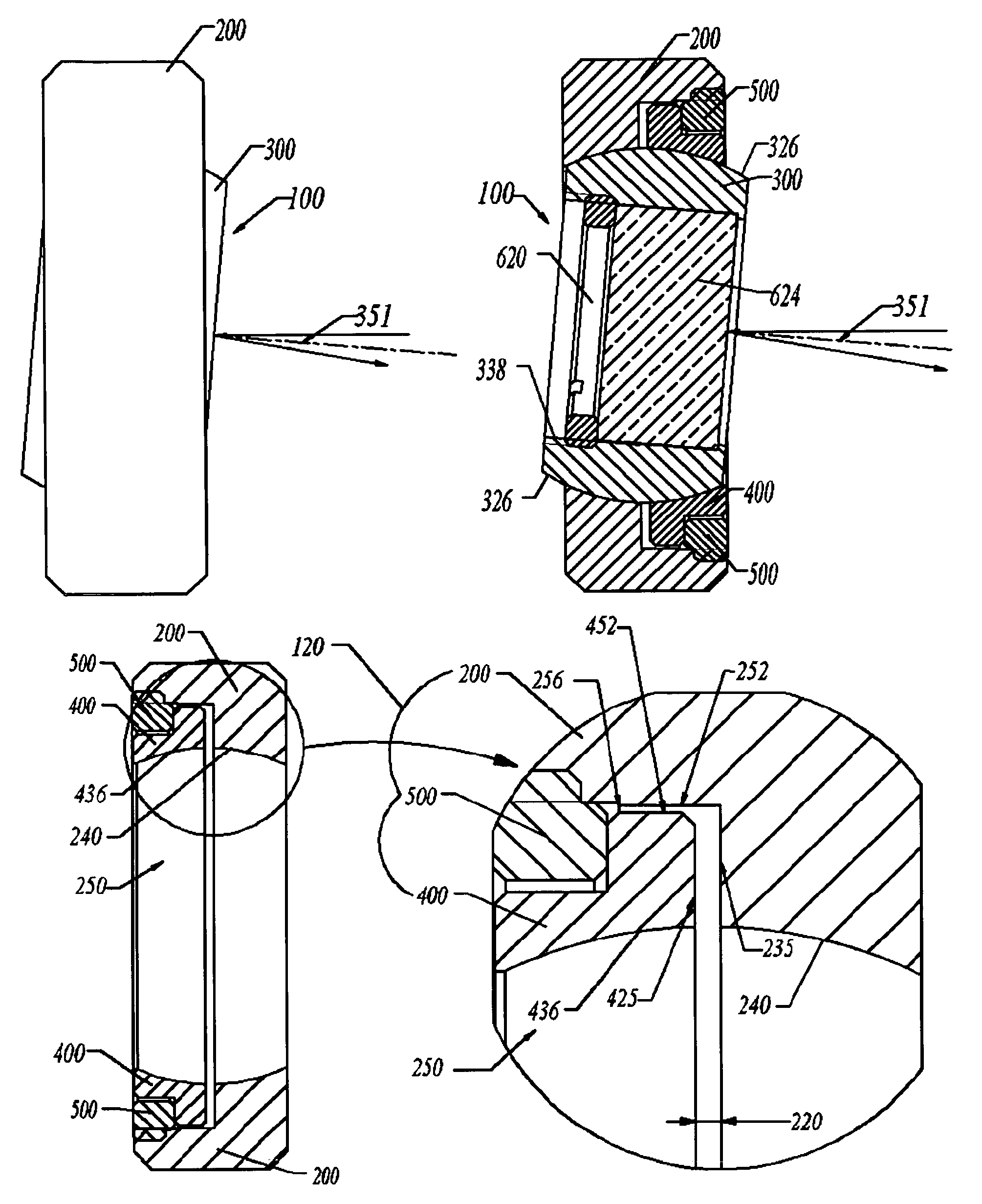
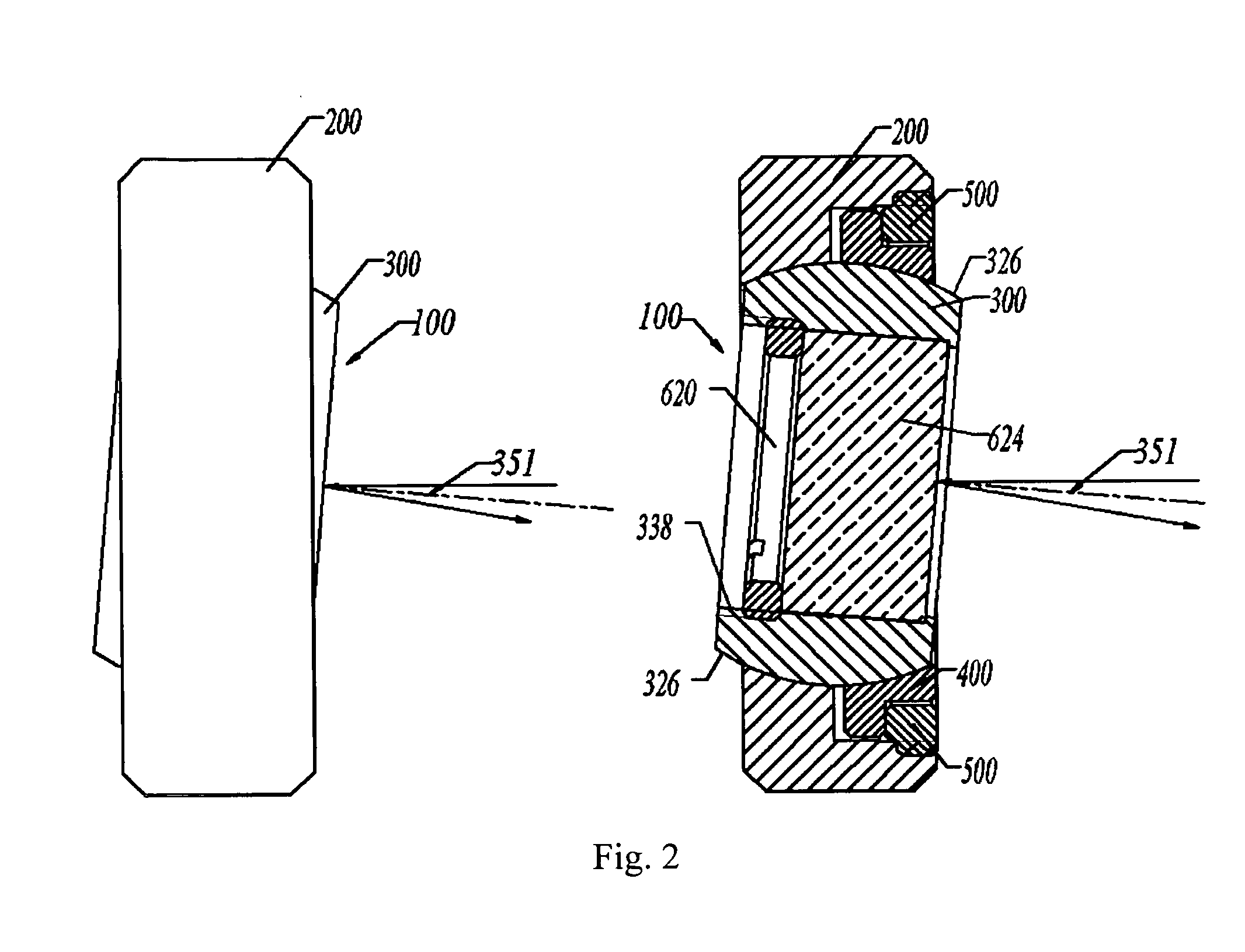
[0036]The Adjustable / Non-adjustable Precision Optical Mounts 100 according to the present invention is disclosed while referring concurrently to FIG. 2-7 and FIG. 11 of the drawings. The optical mount 100 has a stationary plate 200, a movable plate 400, an optical element carrier plate 300 and a locking ring 500.
[0037]As an important detail of the optical mount 100, the stationary plate has a partial-spherical shaped hole 240 (Best shown in FIGS. 6 & 7) that receives the optical element carrier plate 300.
[0038]As another important detail of the optical mount 100, the movable plate 400 has a partial-spherical shaped hole 436 (Best shown in FIGS. 6 & 7).
[0039]Except for a partial-spherical shaped hole 240, the stationary plate has a non-circle step hole 252 as a guiding mechanism, to receive the movable plate 400, a thread hole 262 as a locking ring guiding mechanism to receive the locking ring 500 and a step mechanism for position limit. It should be noted that the partial-spherical ...
second embodiment
[0045]The Adjustable / Non-Adjustable Precision Optical Mounts 101 according to the present invention is disclosed while referring concurrently to FIG. 8-11 of the drawings. The optical mount 101, has a stationary plate 201, a movable plate 401, an external-spherical round shaped optical element carrier plate 300 and a locking ring 500.
[0046]As an important detail of the optical mount 101, the stationary plate has a conical shaped hole 210 (Best shown in FIG. 9).
[0047]As another important detail of the optical mount 101, the movable plate 401 has a conical shaped hole 437 (Best shown in FIG. 9).
[0048]Except for a conical shaped hole 210 of the stationary plate 201, the stationary plate 201 has a non-circle step hole 252 as a guiding mechanism, a thread hole 262 as locking ring guiding mechanism and a step mechanism 256 for position limit.
[0049]For the movable plate 401, except for the conical shaped hole 437, the movable plate has an external non-circle guiding mechanism 452 (Best sho...
third embodiment
[0053]The Adjustable / Non-adjustable Precision Optical Mounts 102 according to the present invention is disclosed while referring concurrently to FIGS. 6-7 and 12-13 of the drawings. The optical mount 102 has a stationary plate 200, a movable plate 400, an external-round column circumference and chamfered edges optical element carrier plate 301 (best shown in FIG. 13) and a locking ring 500.
[0054]FIG. 12 shows that the external-round column circumference and chamfered edges optical element carrier plate 301 mates and fits in the space adjustable combined internal-spherical cavity 250 (FIG. 7) to form a tiltable feature for angle adjustment around axis rotatable joint pair mechanism 272. The external-round column circumference and chamfered edges optical element carrier plate 301 can be tilted for angle adjustment around the center of the space adjustable combined internal-spherical cavity 250 and the optical element 624 that is carried thereby is tilted for angle adjustment. Around t...
PUM
 Abstract
Description
Claims
Application Information