Supercharge Your Innovation With Domain-Expert AI Agents!

Methods and device for ultrasonic range sensing

a technology of ultrasonic range and sensing device, applied in the field of ultrasonic sensors, can solve the problems of ineffective or inaccurate proximity dead zone of proximity detectors using only one range sensor, many ultrasonic range sensors have difficulty in accurately sensing proximate objects within a meter of the sensor,

Active Publication Date: 2010-03-16
PROVIDENTIAL INNOVATIONS LLC
View PDF8 Cites 13 Cited by
  • Summary
  • Abstract
  • Description
  • Claims
  • Application Information

AI Technical Summary

Problems solved by technology

Many ultrasonic range sensors have difficulty sensing proximate objects accurately within a meter of the sensor.
Ultrasonic range detectors that use only one range sensor cannot detect distances up to the front face of the sensor.
These sensors have a proximity dead zone within which they are ineffective or inaccurate.
In contact ultrasonic testing, the area just below the surface of a test object that can not be inspected because of the transducer is still ringing down and not yet ready to receive signals.
Ultrasonic range detectors that use two range sensors cannot detect distances up to the front sensor face because the signal becomes blocked from sensor to sensor.
These detectors also have a proximity dead zone within which they are ineffective or inaccurate.
If it does indicate something is in the dead zone, these detectors will not be able to precisely identify the location of the object relative to the detector.
Thus, a heretofore unaddressed need exists in the industry to address the aforementioned deficiencies and inadequacies.

Method used


Image

  • Methods and device for ultrasonic range sensing
  • Methods and device for ultrasonic range sensing
  • Methods and device for ultrasonic range sensing

Examples


Embodiment Construction

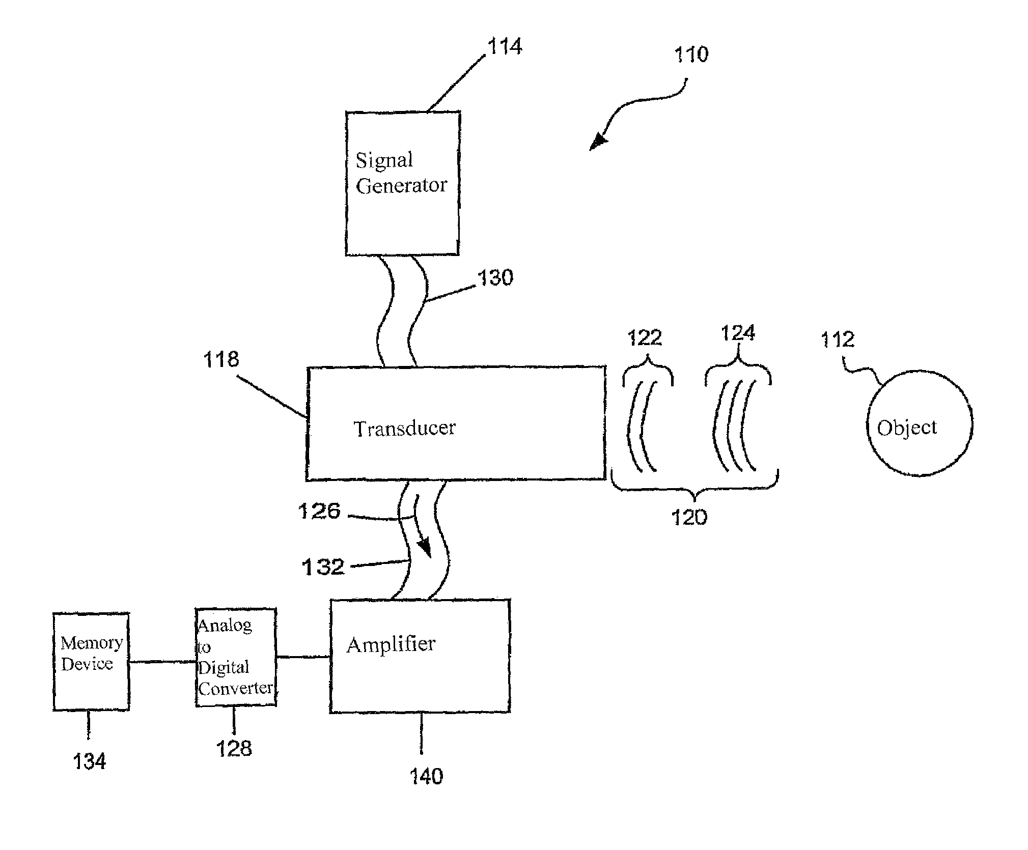
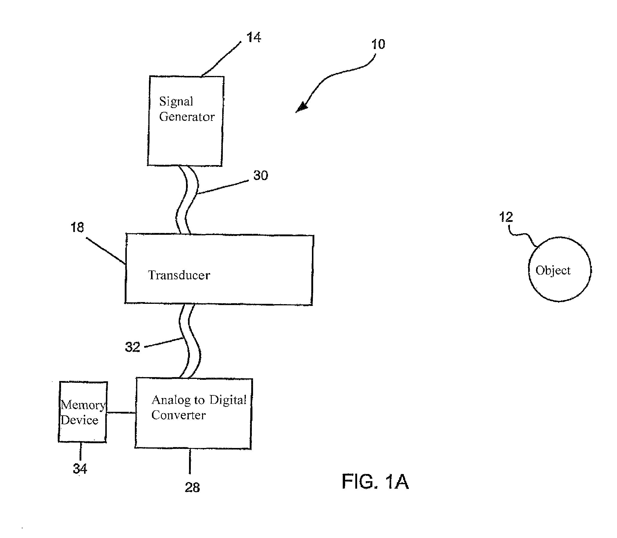
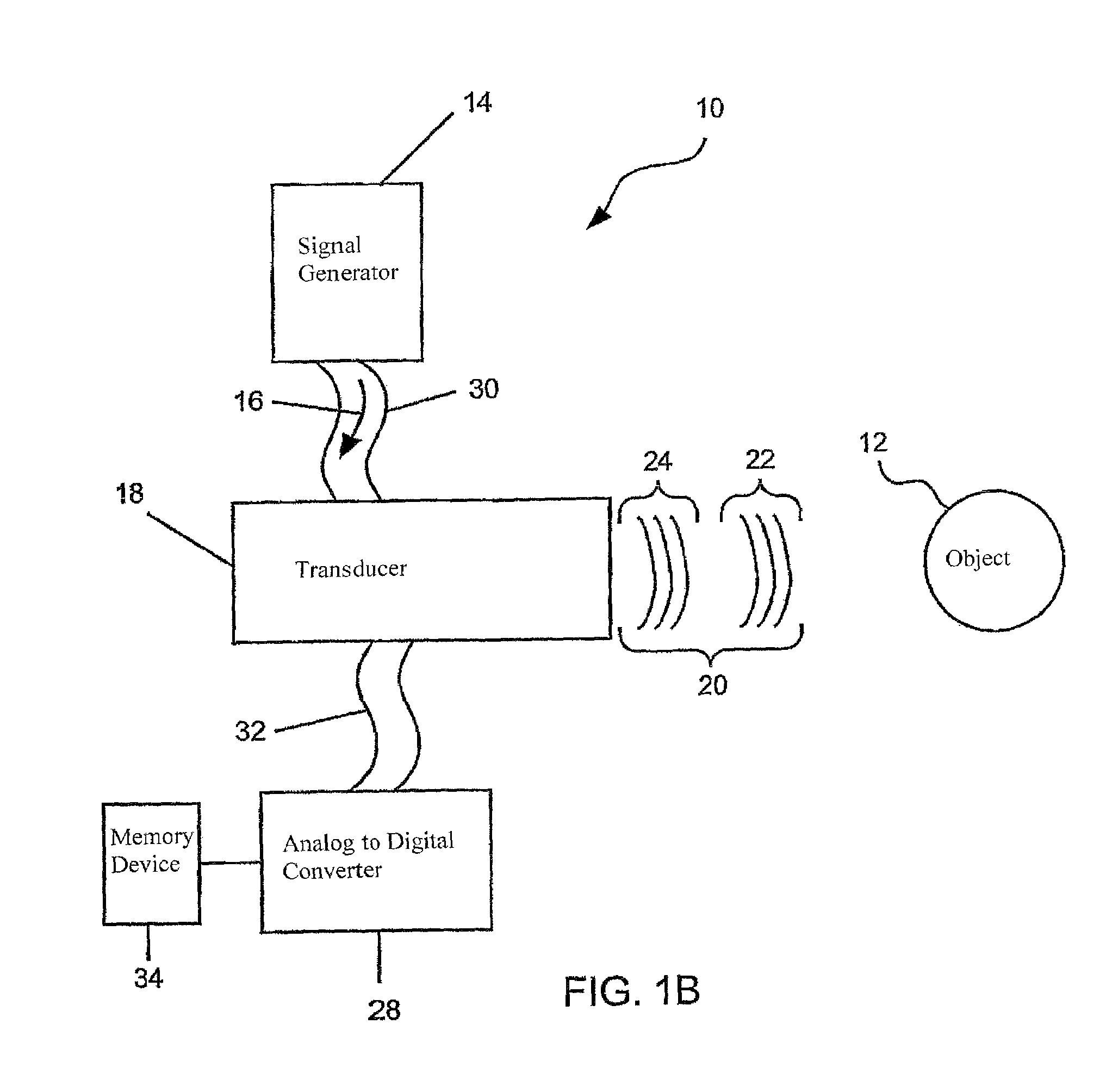
[0013]FIG. 1A, FIG. 1B, and FIG. 1C are a series of block diagrams of a system 10 for sensing proximity of an object 12, in accordance with a first exemplary embodiment of the invention. The system 10 includes a signal generator 14, which generates a plurality of signals 16. A transducer 18 is in communication with the signal generator 14 to receive the plurality of signals 16 from the signal generator 14. The transducer 18 is capable of transforming the plurality of signals 16 from the signal generator 14 into a plurality of ultrasonic waves 20. The plurality of ultrasonic waves 20 includes a first ultrasonic wave 22 and a second ultrasonic wave 24, wherein the first ultrasonic wave 22 and the second ultrasonic wave 24 are formed out of phase. The plurality of ultrasonic waves 20 are directed toward and reflected by the object 12. The transducer 18 receives the plurality of ultrasonic waves 20 reflected by the object 12, which become a plurality of received ultrasonic waves 26. An ...


PUM


Abstract

A system and method for sensing proximity of an object includes a signal generator, which generates a plurality of signals. A transducer is in communication with the signal generator to receive the plurality of signals from the signal generator. The transducer is capable of transforming a plurality of signals from the signal generator into a plurality of ultrasonic waves. The plurality of ultrasonic waves includes a first ultrasonic wave and a second ultrasonic wave, wherein the first ultrasonic wave and the second ultrasonic wave are formed out of phase. The plurality of ultrasonic waves are directed toward and reflected by the object. The transducer receives the plurality of ultrasonic waves reflected by the object, which become a plurality of received ultrasonic waves. An analog to digital converter is in communication with the transducer. The received plurality of ultrasonic waves reflected by the object is communicated to the analog to digital converter by the transducer.

Description

FIELD OF THE INVENTION[0001]The present invention is generally related to electronic sensors and more particularly is related to an ultrasonic sensor with improved range features.BACKGROUND OF THE INVENTION[0002]Range sensors are useful, for instance, in the construction and design of robots. Many ultrasonic range sensors have difficulty sensing proximate objects accurately within a meter of the sensor. As mobile robots programmed to perform specific automation sometimes need to operate with care toward proximate objects, it would be useful for a robot to be able to accurately sense proximate objects.[0003]Ultrasonic range detectors that use only one range sensor cannot detect distances up to the front face of the sensor. These sensors have a proximity dead zone within which they are ineffective or inaccurate. A dead zone, in ultrasonic testing, is the interval following the initial pulse where the transducer ring down prevents detection or interpretation of reflected energy (echoes...

Claims


Application Information

Patent Timeline
IPC IPC(8): G01S15/32
CPCG01S15/08G01S7/52004G01S7/52006
Inventor GROSS, ROBERT RAY
Owner PROVIDENTIAL INNOVATIONS LLC
Features
  • R&D
  • Intellectual Property
  • Life Sciences
  • Materials
  • Tech Scout
  • Unparalleled Data Quality
  • Higher Quality Content
  • 60% Fewer Hallucinations
Learn More