Medical injector systems having an injector plunger that releasably engages a syringe hub upon retraction of the plunger

a technology of injectors and plungers, which is applied in the direction of automatic syringes, packaging goods types, transportation and packaging, etc., can solve the problems of increasing the risk of undesirable infection of patients, increasing the manufacturing assembly cost and complexity of syringes, and reducing the chances of microorganisms entering the fluid and patient, reducing the chance of fluid and patient introduction, and reducing the cost of materials used

Active Publication Date: 2010-03-23
BAYER HEALTHCARE LLC
View PDF30 Cites 118 Cited by
  • Summary
  • Abstract
  • Description
  • Claims
  • Application Information

AI Technical Summary

Benefits of technology

[0145]According to these methods, all outside air is excluded in order to substantially reduce the chances of introducing microbes to the fluid and patient. Furthermore, the method provides a convenient and expedient way of filling and purging both the syringe and the tube in one operation, and as well as reducing costs of materials used and speed of syringe filling as compared with traditional methods. Filling and purging of the syringe and...

Problems solved by technology

The required orientation, however, hinders rapid attachment and replacement of the syringe.
The required orientation may also increase the manufacturing assembly cost and complexity of the syringe.
This practice exposes the fluid to ambient microbes, and allows contamination, and thus increases the risk of undesirable infection of the patient.
However in use, the filling procedure is very tedious, and some fluid is often lost through the filter.
Where large volumes are drawn into the syringe according to known methods, it can be very difficult to simultaneously hold the bottle inverted, and draw back the syringe.
If this is not done, then it is possible that a bubble of air ...

Method used


Image

  • Medical injector systems having an injector plunger that releasably engages a syringe hub upon retraction of the plunger
  • Medical injector systems having an injector plunger that releasably engages a syringe hub upon retraction of the plunger
  • Medical injector systems having an injector plunger that releasably engages a syringe hub upon retraction of the plunger

Examples


Embodiment Construction

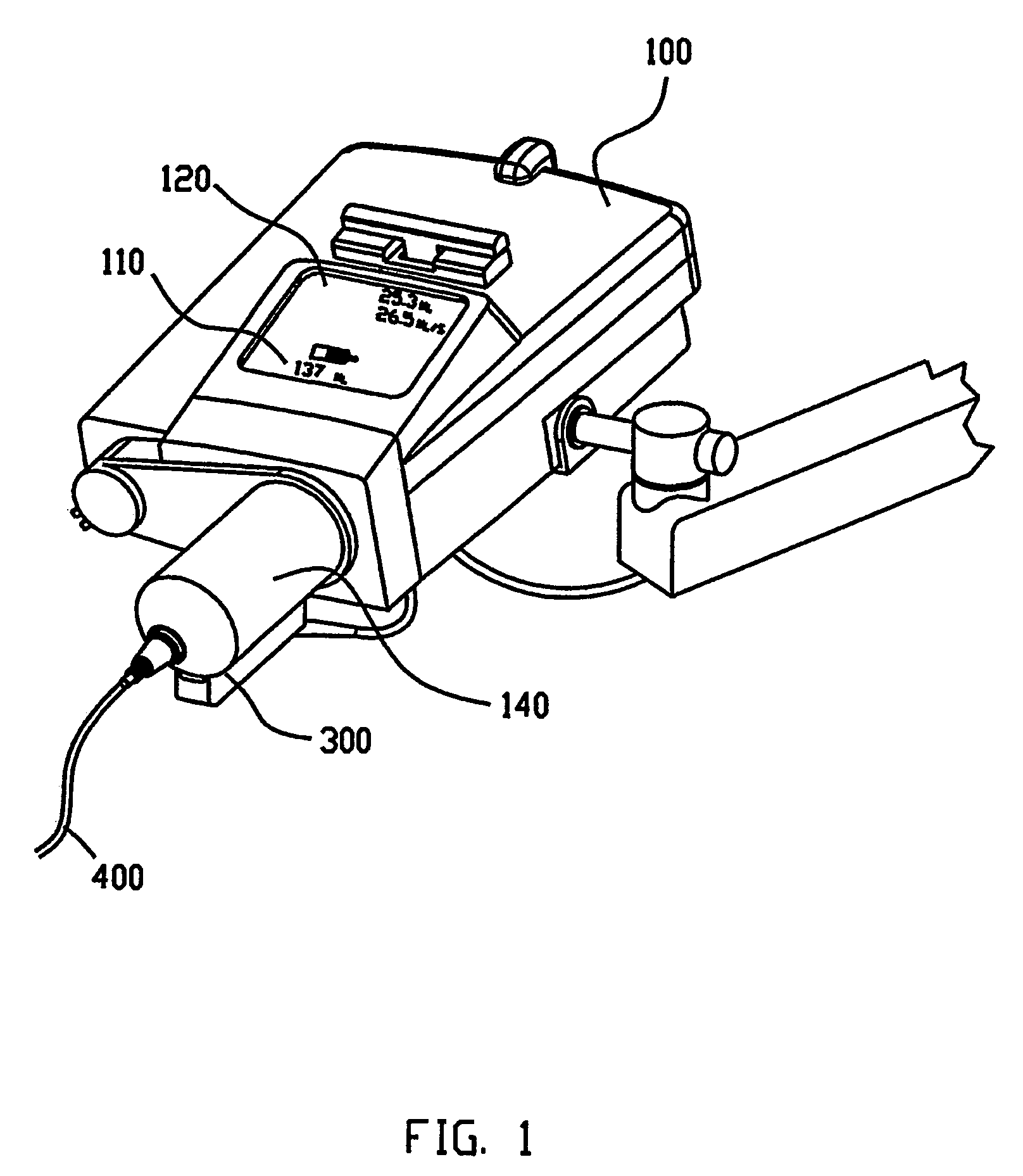
[0260]A typical injector system used for similar applications as the present invention includes an automatic injector device 100. The injector will normally have a data entry pad 110 together with a display 120 for entering data and viewing data respectively. The type of data that may be entered into the system includes injecting rates and volumes. The system according to the prior art includes a pressure jacket or sleeve 140 which is connected to injector 100 for retaining an appropriate syringe 300. Tube 400 connects syringe 300 to the patient (not shown). The prior-art arrangement of the injector as shown in FIG. 1 suffers from a number of disadvantages. Firstly, to install syringe 300 into injector 100, sleeve 140 must first be removed or opened to allow syringe 300 to be rear- or breech-loaded into the sleeve 140 and fixed therein by reattaching or closing sleeve 140. In some cases, sleeve 140 is completely closed, like that shown in FIG. 1, requiring that tube 400 be attached ...


PUM

PropertyMeasurementUnit
Weightaaaaaaaaaa

Abstract

A medical injector system for injecting fluid from a syringe (300) into a patient, the syringe (300) having a barrel (300) and a plunger (310), the plunger (310) comprising an inner surface having an engaging portion (311) adapted to be releasably engaged by a plunger handle (130) which has a retention member (142) adapted to releasably engage the engaging portion (311) of the plunger (310); and a syringe holder comprising a cradle member (200) adapted to receive a barrel (300) of the syringe (300) and a pivotable catch (500) to releasably lock the syringe (300) in the cradle member (200).

Description

FIELD OF THE INVENTION[0001]The present invention relates to medical injector systems for injecting medical fluids into a patient's vascular system.BACKGROUND OF THE INVENTION[0002]Medical injectors and syringes for injecting contrast media into a patient for imaging biological structures are known in the art. For example, U.S. Pat. No. 4,677,980, issued to D. M. Reilly et al. on Jul. 7, 1987, and entitled “Angiographic Injector and Angiographic Syringe for Use Therewith,” which is assigned to the same Assignee as the subject application, discloses an angiographic injector apparatus. The apparatus is designed for injecting contrast media into the vascular system of an animal, in which syringes are rear-loaded into a pressure jacket of the injector. More specifically, the apparatus comprises a rotatable turret which carries a pair of the pressure jackets and which is rotatable so that when one of the pressure jackets, into which a syringe has been rear-loaded, is in an injection posi...

Claims


Application Information

Patent Timeline
IPC IPC(8): A61M1/00A61M5/315A61M5/00A61M5/20A61M5/145A61M5/34A61M5/36A61M5/50
CPCA61M5/007A61M5/14546A61M5/14566A61M5/1458A61M5/31513A61M5/31515A61M5/347A61M5/348A61M5/36A61M5/5066A61M2005/14553A61M2205/11A61M2205/14A61M2205/215A61M2205/587A61M2205/60
Inventor SAVAGE, RODNEY BRIAN
Owner BAYER HEALTHCARE LLC
Why Eureka
Try Eureka