
Laser warning receiver to identify the wavelength and angle of arrival of incident laser light

a laser light and wavelength technology, applied in the direction of instruments, instruments, instruments for comonautical navigation, etc., can solve the problems that the laser source poses a risk to people either on the ground or piloting an aircraft, and achieve the effect of increasing the angle of arrival and reducing the amount of ligh

Active Publication Date: 2010-03-23
NAT TECH & ENG SOLUTIONS OF SANDIA LLC
View PDF7 Cites 56 Cited by
  • Summary
  • Abstract
  • Description
  • Claims
  • Application Information

AI Technical Summary

Benefits of technology

[0009]The present invention further relates to a laser warning receiver which comprises a plurality of optical channels, with each optical channel receiving laser light from a different angle of arrival. The optical channels comprise a transparent plate that includes a lens for each optical channel on one side of the transparent plate, and an optical wedge for each optical channel on an opposite side of the transparent plate. Each optical channel also comprises a multi-wavelength photodetector to detect the laser light received by that optical channel and to generate therefrom an electrical signal indicative of the angle of arrival of the laser light and the wavelength of the laser light. Each optical channel can further include a baffle to reduce an amount of light that reaches the multi-wavelength photodetector located in that optical channel from angles other than the angle of arrival for that optical channel. In certain embodiments of the present invention, another optical wedge for each optical channel can be located on another transparent plate which is located proximate to the transparent plate containing each lens. This can be useful to increase the angle of arrival for each optical channel.

Problems solved by technology

Laser sources pose a risk to people either on the ground or piloting an aircraft since they can produce temporary flash blindness or even permanent blindness.

Method used


Image

  • Laser warning receiver to identify the wavelength and angle of arrival of incident laser light
  • Laser warning receiver to identify the wavelength and angle of arrival of incident laser light
  • Laser warning receiver to identify the wavelength and angle of arrival of incident laser light

Examples


Embodiment Construction

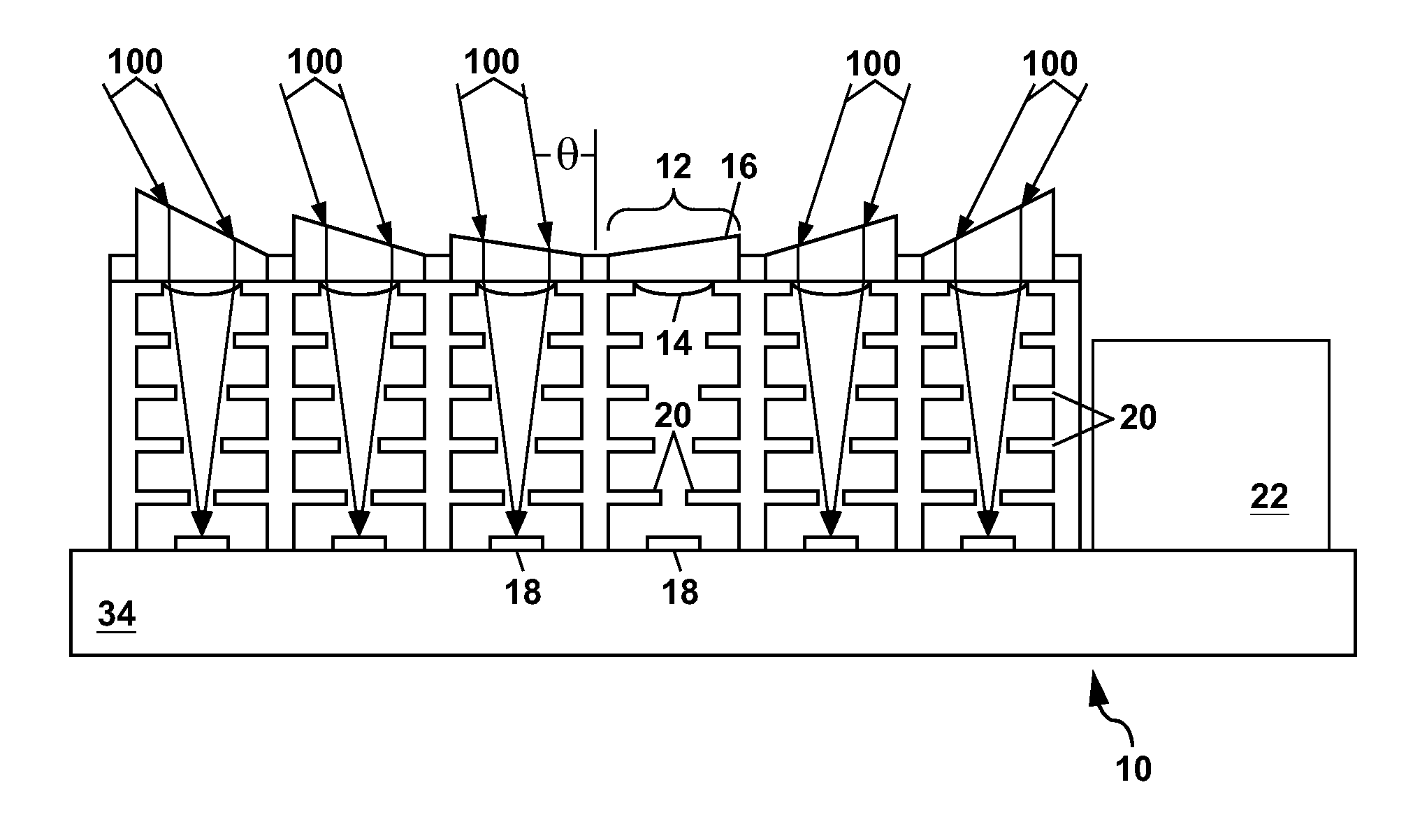
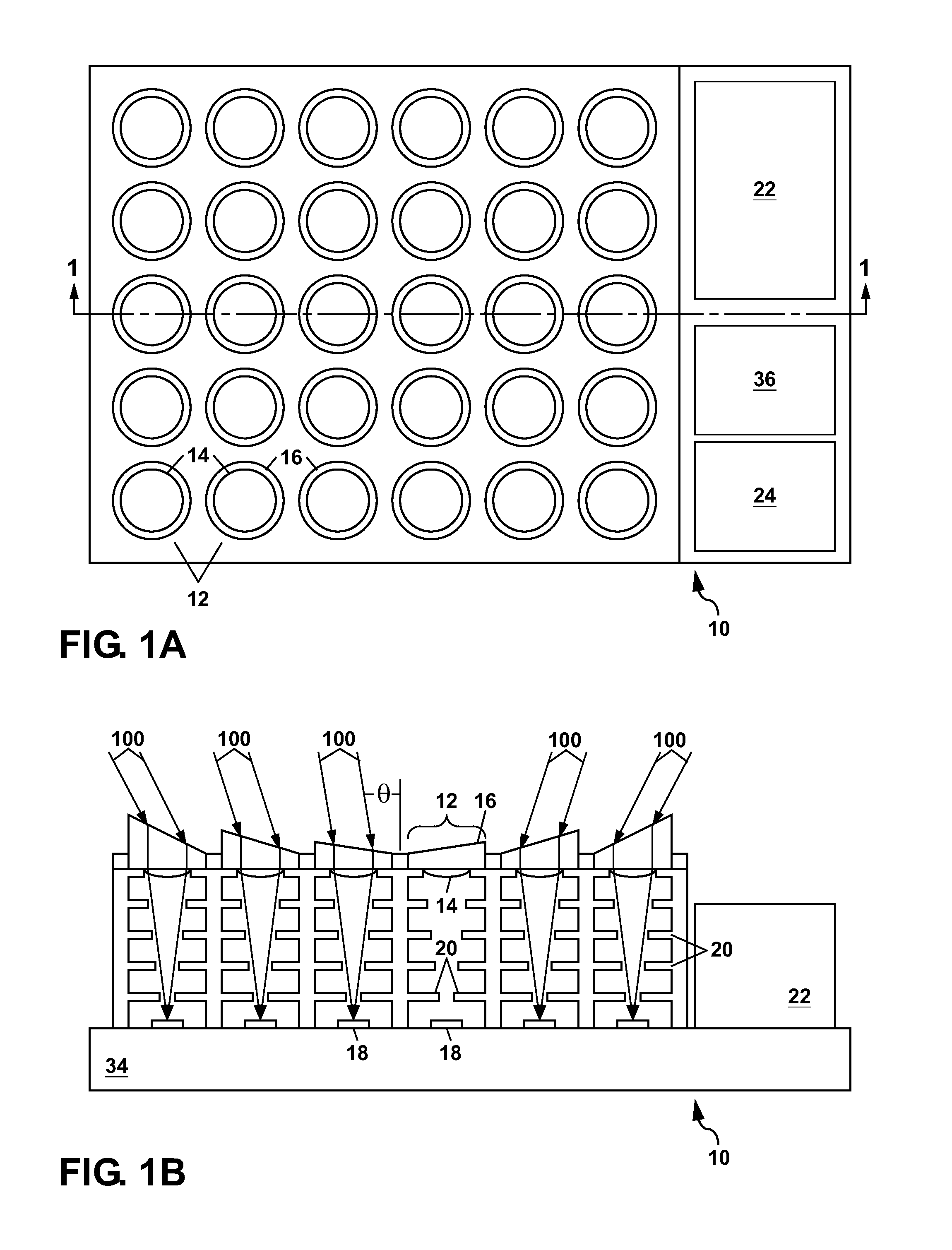
[0026]Referring to FIGS. 1A and 1B, there is shown a schematic plan view and a schematic cross-section view, respectively, of a first example of a laser warning receiver 10 formed according to the present invention. The apparatus 10 comprises a plurality of optical channels 12 (also referred to herein as simply channels) which are each optically oriented to receive laser light 100 from a different angle of arrival θ. Laser light 100, which is directed towards the laser warning receiver 10 at the angle of arrival θ for a particular channel 12 can be received by optics which comprises a lens 14 (also termed a microlens) and an optical wedge 16 (also termed a prism).

[0027]The optical wedge 16 can be circular or polygonal in plan view as shown in FIG. 1A, and has two non-parallel plane faces as shown in FIG. 1B. The optical wedge 16 functions to change the direction of the incoming laser light 100, which is within the angle of arrival θ for a particular optical channel 12, so that the l...


PUM


Abstract

A laser warning receiver is disclosed which has up to hundreds of individual optical channels each optically oriented to receive laser light from a different angle of arrival. Each optical channel has an optical wedge to define the angle of arrival, and a lens to focus the laser light onto a multi-wavelength photodetector for that channel. Each multi-wavelength photodetector has a number of semiconductor layers which are located in a multi-dielectric stack that concentrates the laser light into one of the semiconductor layers according to wavelength. An electrical signal from the multi-wavelength photodetector can be processed to determine both the angle of arrival and the wavelength of the laser light.

Description

GOVERNMENT RIGHTS[0001]This invention was made with Government support under Contract No. DE-AC04-94AL85000 awarded by the U.S. Department of Energy. The Government has certain rights in the invention.FIELD OF THE INVENTION[0002]The present invention relates to laser warning receivers for detecting laser sources which are directed at the laser warning receivers, and for identifying an angle of arrival and a wavelength of any received laser light from such sources.BACKGROUND OF THE INVENTION[0003]Laser sources pose a risk to people either on the ground or piloting an aircraft since they can produce temporary flash blindness or even permanent blindness. Laser sources can also be used to direct munitions and laser-guided missiles; and they can also disable satellite borne imaging systems. To protect against the various threats posed by laser sources, laser warning receivers are needed.[0004]The present invention provides a laser warning receiver which is compact, and which can be used ...

Claims


Application Information

Patent Timeline
IPC IPC(8): H01J3/14H01J5/16
CPCG01S7/4804
Inventor SINCLAIR, MICHAEL B.SWEATT, WILLIAM C.
Owner NAT TECH & ENG SOLUTIONS OF SANDIA LLC
Features
  • Generate Ideas
  • Intellectual Property
  • Life Sciences
  • Materials
  • Tech Scout
  • Unparalleled Data Quality
  • Higher Quality Content
  • 60% Fewer Hallucinations
Learn More