Amplifier topology and method for connecting to printed circuit board traces used as shunt resistors

Active Publication Date: 2010-03-23
TEXAS INSTR INC
View PDF2 Cites 16 Cited by
  • Summary
  • Abstract
  • Description
  • Claims
  • Application Information

AI Technical Summary

Benefits of technology

[0012]It is an object of the invention to provide a current sensing amplifier which makes it practical to

Problems solved by technology

The use of current sensing amplifiers to accurately sense the voltage drop across a portion of a copper trace on a printed circuit board over a normal operating temperature range of −40 to +125 degrees Centigrade is problematic b

Method used


Image

  • Amplifier topology and method for connecting to printed circuit board traces used as shunt resistors
  • Amplifier topology and method for connecting to printed circuit board traces used as shunt resistors
  • Amplifier topology and method for connecting to printed circuit board traces used as shunt resistors

Examples


Embodiment Construction

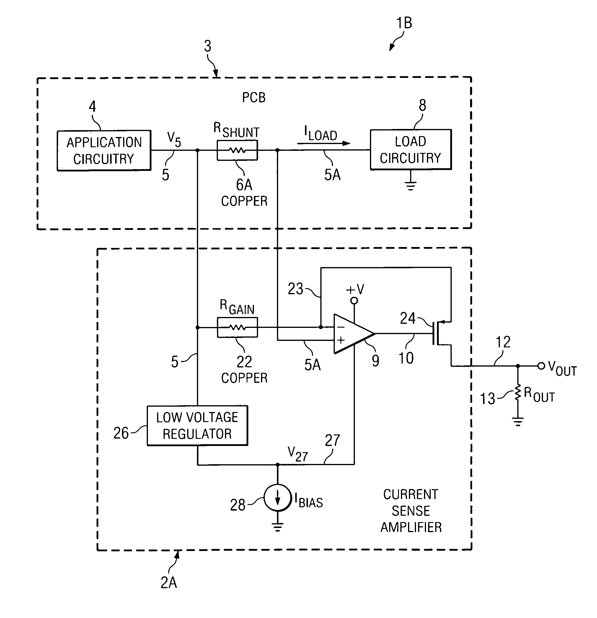
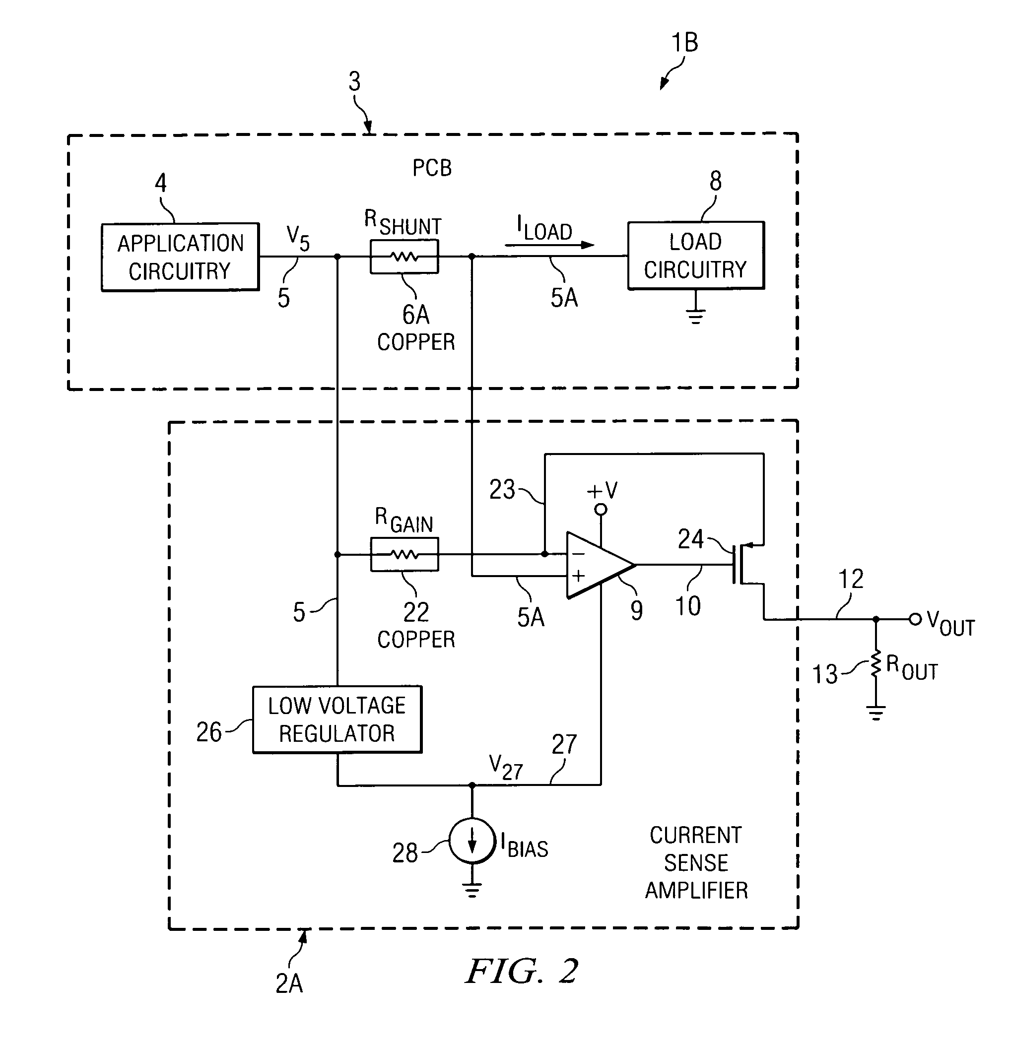
[0027]Referring to FIG. 2, circuitry 1B includes a current sensing amplifier 2A connected to measure the voltage drop produced across shunt resistor 6A by load current ILOAD. Printed circuit board 3 includes application circuitry 4 connected by copper trace conductor 5 to one terminal of shunt resistor 6A. Application circuitry 4 produces a voltage V5 on copper trace conductor 5. The other terminal of shunt resistor 6A is connected by copper trace conductor 5A to load circuitry 8, which may be located on or off printed circuit board 3. Shunt resistor 6A, which has a resistance RSHUNT, preferably is a section of a copper trace conductor 5,6A,5A which also includes copper trace conductors 5 and 5A on printed circuit board 3.

[0028]By way of definition, if shunt resistor RSHUNT is a section 6A of copper trace conductor 5,6A,5A, then the boundaries of the section 6A at which current-sensing amplifier 2A makes electrical contact to section 6A are referred to herein as “terminals” of shunt...


PUM


Abstract

An integrated circuit current shunt amplifier (2A) includes an amplifier (9) having a (+) input connected to a first terminal (5A) of a shunt resistor (RSHUNT). An output transistor (24) has a gate coupled to an output of the amplifier, a source coupled to a (−) input of the amplifier, and a drain coupled to a first terminal of an output resistor (ROUT). A gain resistor (RGAIN) is coupled between the (−) input of the amplifier and a second terminal of the shunt resistor. The gain resistor has a temperature coefficient which is essentially the same as that of the shunt resistor. A voltage regulator (26) can be coupled between the second terminal of the shunt resistor and a low-side supply voltage terminal (27) of the amplifier. A charge pump (30) can provide a below-ground voltage on a second terminal of the output resistor. A difference amplifier (31) coupled to the drain and referenced to the below-ground voltage produces an output voltage (Vout) referenced to ground.

Description

BACKGROUND OF THE INVENTION[0001]The present invention relates generally to current sensing amplifiers, and more particularly to a current sensing amplifier which is capable of accurately sensing current flowing through a trace conductor on a printed circuit board (PCB) and providing instant, automatic temperature compensation of the sensed value by means of a gain resistor that is included within the current sensing amplifier and is composed of essentially the same kind of material as the trace conductor.[0002]It would be desirable to have a highly accurate current sense amplifier that can be used when there is a need for precise measurement of current flowing in a PCB conductor. Furthermore, even if a particular application does not require accurate measurement of the amount of current flowing into a load to accomplish a primary function of the application, it nevertheless often is desirable to have an accurate, temperature-compensated value representing the voltage drop in a copp...

Claims


Application Information

Patent Timeline
IPC IPC(8): G01R1/30
CPCG01R1/30G01R1/203
Inventor STEELE, GERALD W.MULLINS, EDWARD
Owner TEXAS INSTR INC
Why Eureka
Try Eureka