Flexible display testing and inspection

a display panel and flexible technology, applied in the direction of electronic circuit testing, measurement devices, instruments, etc., can solve the problems of damage to the display panel, ineffective and cost-effective testing and inspection, and operator injury,

Inactive Publication Date: 2010-03-23
E INK CALIFORNIA
View PDF11 Cites 128 Cited by
  • Summary
  • Abstract
  • Description
  • Claims
  • Application Information

AI Technical Summary

Problems solved by technology

The use of a temporary conductive layer therefore is not an efficient and cost-effective way for testing and inspection.
This could cause damage to the display panel, even cause injury to the operator.
Besides, the method can only be performed in a sheet-by-sheet manner, not suitable for roll-to-roll in-line inspection.

Method used


Image

  • Flexible display testing and inspection
  • Flexible display testing and inspection
  • Flexible display testing and inspection

Examples


Embodiment Construction

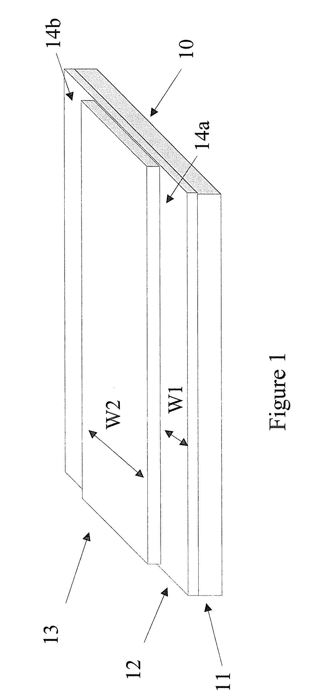
[0049]FIG. 1 shows a flexible display panel typically used in the present methods. As shown, the display panel (10) comprises a transparent substrate (11) (e.g., PET), a transparent conductive layer (12) (e.g., ITO) and a layer of display cells filled with a display fluid. For brevity, the layer of display cells filled with a display fluid may be referred to as a display medium layer (13).

[0050]There may be an adhesive layer (not shown) present between the transparent conductive layer (12) and the display medium layer (13) or on top of the display medium layer.

[0051]The transparent conductive layer (12) may either cover the entire surface of the transparent substrate or be patterned. The commercially available conductive layer (12) usually is supplied on a substrate (11). There may be other material layers on the conductive layer (12), opposite from the display medium layer; however, it is not essential to have the extra layers.

[0052]Normally, one of the edges (14a and 14b) of the t...


PUM

PropertyMeasurementUnit
conductiveaaaaaaaaaa
ground voltageaaaaaaaaaa
voltageaaaaaaaaaa

Abstract

The present invention provides methods and systems for testing and inspection of a display panel. The methods involve the application of voltages to rollers or testing conductive films. By applying a potential difference to the appropriate rollers or testing conductive films, different optical states of a display panel can be displayed for inspection.

Description

[0001]This application claims priority to U.S provisional application No. 60 / 809,045, filed May 26, 2006. The content of which is incorporated herein by reference in its entirety.FIELD OF THE INVENTION[0002]The present invention provides methods and systems for testing and inspection of a display panel.BACKGROUND OF THE INVENTION[0003]The electrophoretic display (EPD) is a non-emissive device based on the electrophoresis phenomenon influencing the migration of charged pigment particles in a solvent, preferably in a dielectric solvent. More specifically, an electrophoretic fluid comprising charged pigment particles dispersed in a dielectric solvent is enclosed between two electrode plates. At least one of the electrode plates is transparent and such a transparent plate is usually the viewing side. When a voltage difference is imposed between the two electrode plates, the charged pigment particles migrate by attraction to the electrode plate of polarity opposite that of the charged pi...

Claims


Application Information

Patent Timeline
Patent Type & Authority Patents(United States)
IPC IPC(8): G01R31/02G09G3/34G02F1/167
CPCG02F1/133305G02F1/167
Inventor KANG, GARY YIH-MINGLIU, JOHN HANANWANG, WANHENGCHAUG, YI-SHUNG
Owner E INK CALIFORNIA
Why Eureka
Try Eureka