Heat dissipation device

a heat dissipation device and heat dissipation fin technology, which is applied in the direction of electrical apparatus casings/cabinets/drawers, stoves or ranges, instruments, etc., can solve the problems of insufficient heat dissipation, heat dissipation efficiency could be affected, and the heat dissipation device composed of heat dissipating fins and fans could not meet the heat dissipation requirement, so as to improve heat dis

Active Publication Date: 2010-03-23
CELSIA TECH TAIWAN INC
View PDF15 Cites 19 Cited by
  • Summary
  • Abstract
  • Description
  • Claims
  • Application Information

AI Technical Summary

Benefits of technology

[0005]The present invention relates to a heat dissipation device, the heat dissipation device includes a cover covering on a heat dissipating fins assembly and a fan. The airflow from the fan can be centralized to dissipate heat from the heat dissipating fins assembly and a vapor chamber directly to enhance the efficiency of the heat dissipation.
[0006]The present invention relates to a heat dissipation device, the heat dissipation device includes a bent vapor chamber to enhance a heat conducting area thereof to enhance the efficiency of the heat dissipation.
[0007]The present invention relates to a heat dissipation device, the heat dissipation device includes a bent vapor chamber on opposite sides thereof to avoid interference with the other electronic elements of the mainboard to achieve a better applicability of installation.

Problems solved by technology

A conventional heat dissipation device composed of heat dissipating fins and a fan could not meet the heat dissipating requirement of the CPU.
However, the conventional heat dissipation device has following disadvantage in practice use: when the fan dissipating heat from the heat dissipating fins assembly and the vapor chamber, the airflow can not be centralized effectively causing insufficient heat dissipation.
Thus, the heat dissipating efficiency could be affected.
Additionally, the vapor chamber is made in flat shape, however the outer surface thereof is adhered to the heat generating element completely, and further the heat conducting area is limited to the outer surface of the heat generating element.
Thus, the heat dissipating efficiency can not be further improved efficiently.
If the vapor chamber is broaden to enlarge the outer surface thereof, the other electronic elements on the circuit board may be intervened accordingly to cause the heat dissipation device not be appropriately installed and not be used therefore.

Method used


Image

  • Heat dissipation device
  • Heat dissipation device
  • Heat dissipation device

Examples


Embodiment Construction

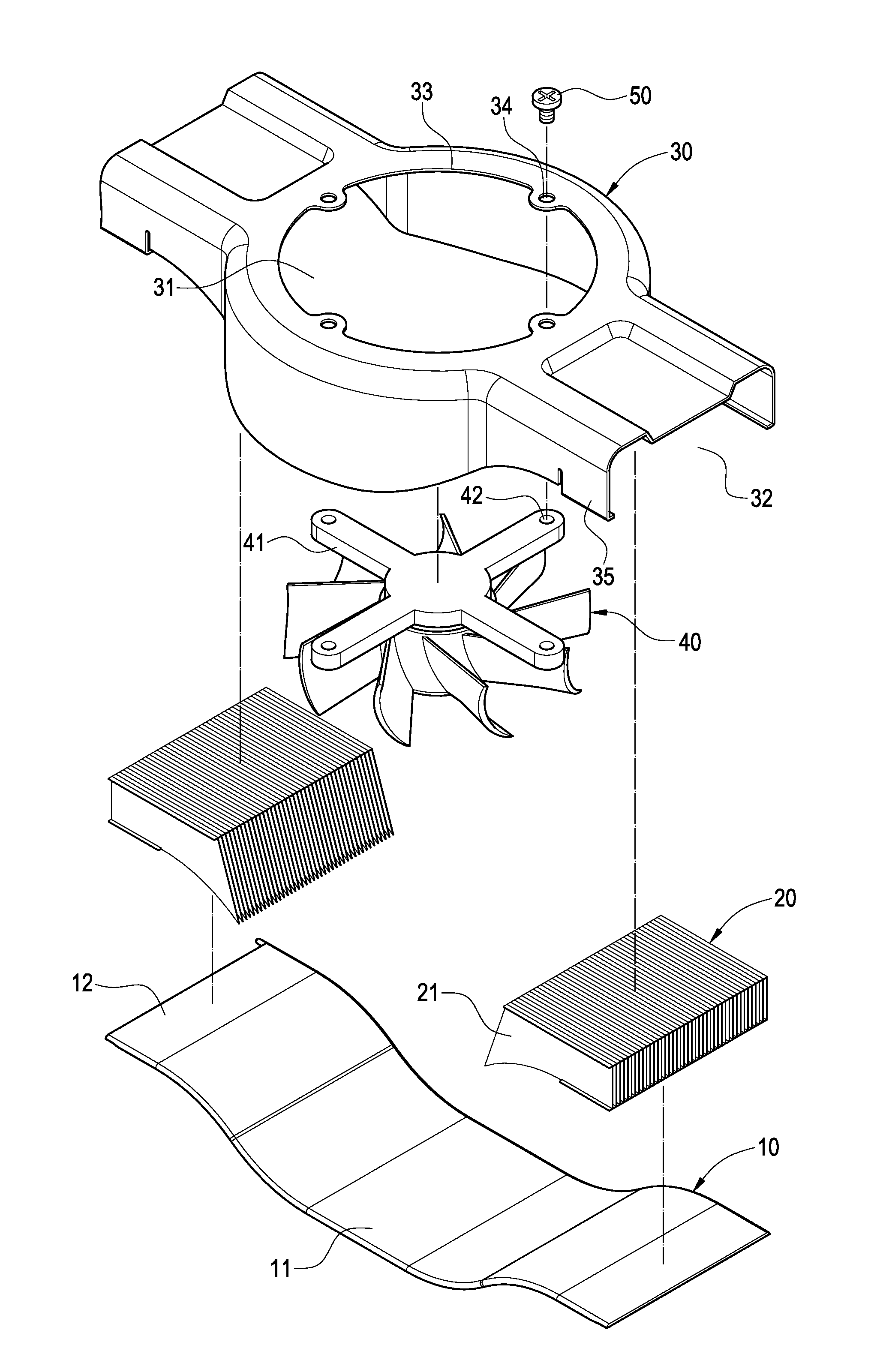
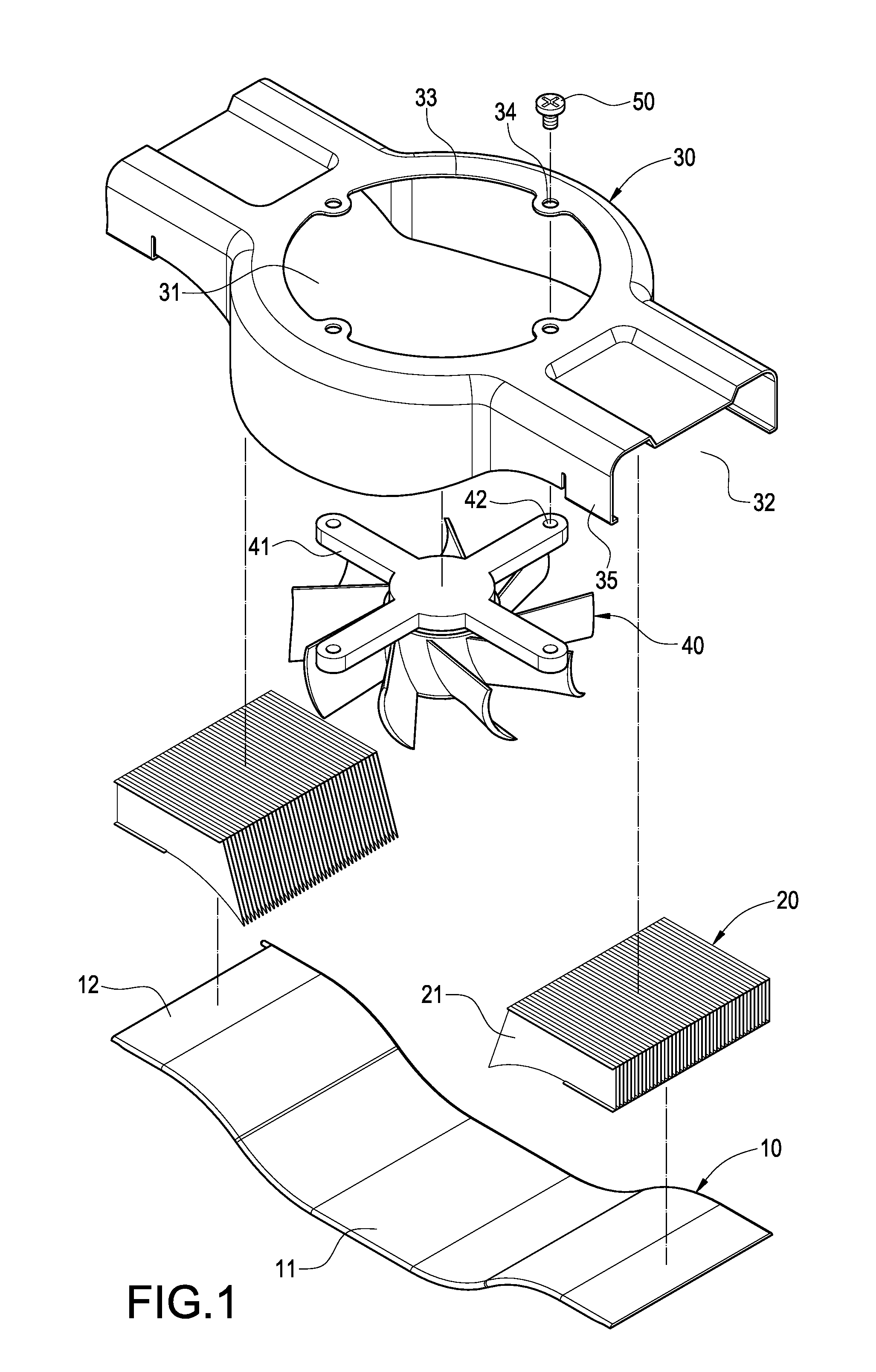
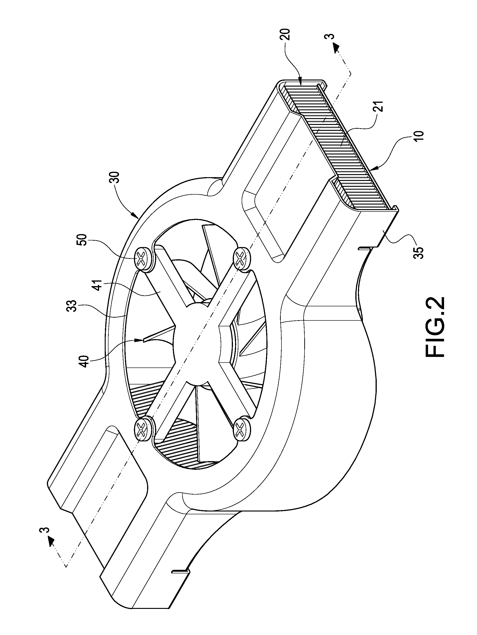
[0015]Referring to FIG. 1 and FIG. 4, a heat dissipation device of an exemplary of the present invention includes a vapor chamber 10, a heat dissipating fins assembly 20, a cover 30 and a fan 40.

[0016]The vapor chamber 10 is made in a strip structure and is configured to a bent shape. The vapor chamber 10 includes a heat absorbing portion 11 and two heat emitting portion 12 deformedly extending from opposite sides of the absorbing portion 11. The absorbing portion 11 protrudes from the surface of the emitting portions 12. The absorbing portion 11 is adhered to a surface of a heat generating element 62 (as shown in FIG. 5). A large heat dissipating area is configured at the heat dissipating portion 12 and heat absorbing portion 11. The heat generating element 62 is a CPU, a semiconductor packing part, a wafer or other electronic elements with high heat generation.

[0017]The heat dissipating fins assembly 20 is adhered to a partial surface of the vapor chamber 10, preferrably, the heat...


PUM


Abstract

A heat dissipation device includes a vapor chamber, a heat dissipating fins assembly, a cover and a fan. The vapor chamber is configured to a bent shape. The heat dissipating fins assembly is adhered to a partial surface of the vapor chamber. The cover is connected to the vapor camber. A flow passage is defined between the vapor chamber and the cover. The heat dissipating fins assembly is positioned in the flow passage. The cover defines an opening communicating to the flow passage. The fan is arranged facing to the opening of the cover and other partial surface of the vapor chamber. Therefore, the heat dissipating efficiency can be greatly improved.

Description

BACKGROUND[0001]The present invention relates to a heat dissipation device, and particularly to a heat dissipation device with a bent vapor chamber.[0002]With enhancement of the calculating capability of the central processing unit (CPU), the heat generates from the CPU is becoming greater than before. A conventional heat dissipation device composed of heat dissipating fins and a fan could not meet the heat dissipating requirement of the CPU. A vapor chamber with higher heat conducting efficiency is developed. The vapor chamber is combined with the heat dissipating fins to effectively resolve the heat dissipating problems. The vapor chamber could contact the heat generating electronic element in a large area directly, and these advantages could draw more development on the merit.[0003]A conventional heat dissipation device includes a vapor chamber, a heat dissipating fins assembly and a fan. The vapor chamber is configured to a flat shape, and the vapor chamber is adhered to a surfa...

Claims


Application Information

Patent Timeline
Patent Type & Authority Patents(United States)
IPC IPC(8): H05K7/20H01L23/36
CPCF28D15/0233H01L23/467H01L2924/0002H01L2924/00
Inventor MEYER, IV, GEORGE ANTHONYSUN, CHIEN-HUNG
Owner CELSIA TECH TAIWAN INC
Why Eureka
Try Eureka