
Free-wheeling clutch for a motor control center subunit having moveable line contacts

a technology of free-wheeling clutch and motor control center, which is applied in the direction of switchgear arrangement, switchgear with a retractable carriage, electrical apparatus construction details, etc., can solve the problems of manual manipulation of line connections or stabs, overdrive of pivot line connectors and other components,

Active Publication Date: 2010-03-23
EATON INTELLIGENT POWER LTD
View PDF18 Cites 37 Cited by
  • Summary
  • Abstract
  • Description
  • Claims
  • Application Information

AI Technical Summary

Benefits of technology

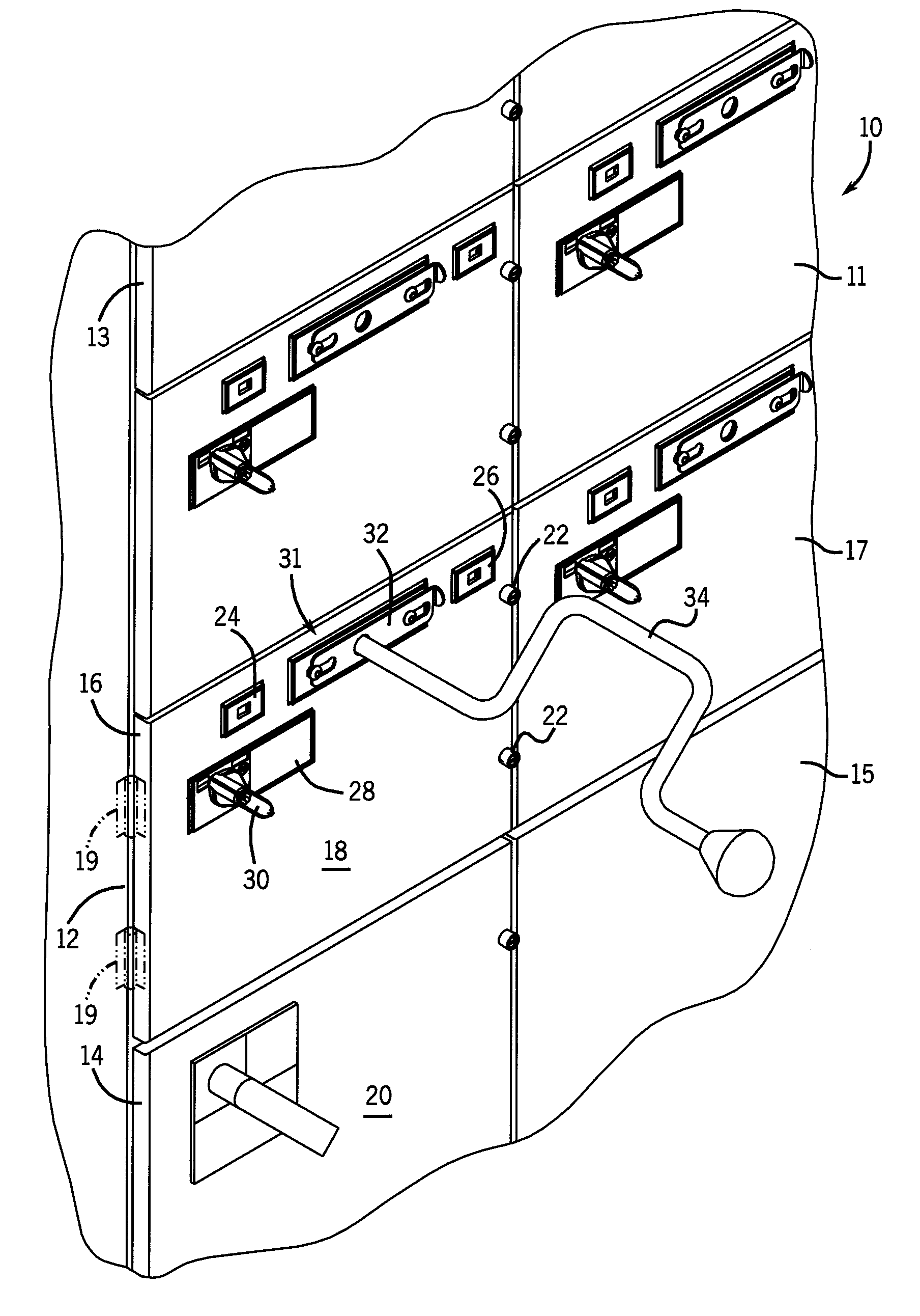
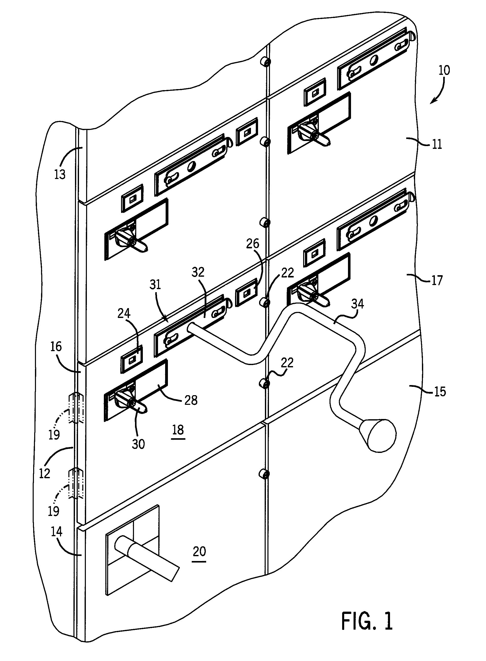
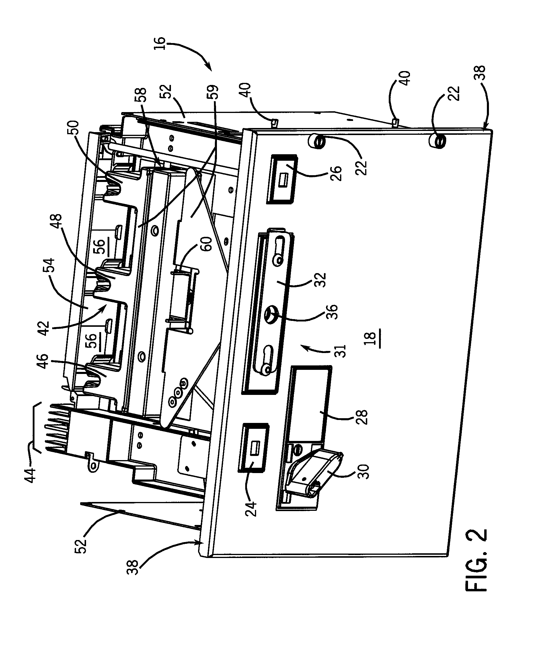
The present invention provides a system and method for installing a motor control center subunit and connecting motor control components to a power supply. The system uses moveable line stabs to contain potential arc flashes. The motor control center subunit includes a housing, a drive mechanism, and a freewheeling mechanism to define the position of conductive contacts. The invention also includes an actuating mechanism to control movement of the conductive contacts and a clutch to define the range of movement. The motor control center subunit can be easily installed in a motor control center frame and includes a means to prevent the actuating mechanism from translating beyond certain positions. The technical effects of the invention include improved safety and reliability in the installation and operation of motor control centers.

Problems solved by technology

The line connections or stabs may be difficult to maneuver manually when an operator is supporting the entire bucket or when the stabs are not visible.
However, many of these systems require that the bucket or compartment door be open to manipulate the handles and line stabs.
Additionally, these systems can subject the pivot line connectors and other components to overdrive and / or overtorquing, as the system includes solid stops when manipulating the connectors between racking in and extracting out positions.

Method used


Image

  • Free-wheeling clutch for a motor control center subunit having moveable line contacts
  • Free-wheeling clutch for a motor control center subunit having moveable line contacts
  • Free-wheeling clutch for a motor control center subunit having moveable line contacts

Examples


Embodiment Construction

[0032]The following description makes reference to supply power, supply power lines, motor power, load power, line power, and the like. It is appreciated that such terms may refer to a variety of both common and uniquely conditioned voltage and current characteristics, including but not limited to, three phase AC power, single phase AC power, DC power, multiple DC power lines, or any combination thereof. Such power characteristics will be generally referred to as being provided on a bus, supply line, or riser of a motor control center. However, it is appreciated that the present invention may find applicability in other power connectivity configurations, adapted or apart from motor control centers. An example of supply power commonly used in motor control centers is 480V three-phase AC power distributed over three separate supply bus bars. In addition, references to “motor control components” shall be understood to include the various types of devices and control components which ma...


PUM


Abstract

A system and method for connecting supply power to motor control components includes use of a motor control center subunit with moveable supply power contacts. After a motor control center subunit is secured into a motor control center compartment, the supply power contacts may be advanced to engage supply power buses. For disconnection, the supply power contacts may be retracted and isolated from the buses before physical removal of the subunit. A free wheeling mechanism prevents supply power contacts from advancing and retracting past a preset travel range.

Description

BACKGROUND OF THE INVENTION[0001]The present invention relates generally to motor control systems, and more particularly, to a motor control center subunit having a clutch system which governs the limits of extension and retraction of power circuitry within the motor control center subunit. In one embodiment, the system and method described herein allow translation of power circuitry along a threaded drive after full installation of the motor control center subunit into the motor control center. Translation of the power circuitry occurs between a position wherein the power circuitry is engaged with a power bus and a position wherein the power circuitry is retracted from the power bus. Once power circuitry reaches either the engaged or retracted position, the clutch system causes the drive to spin freely and thus prevents movement past either the engaged or retracted position.[0002]A motor control center is a multi-compartment steel enclosure with a bus system to distribute electrica...

Claims


Application Information

Patent Timeline
Patent Type & Authority Patents(United States)
IPC IPC(8): H05K7/16
CPCH02B11/127H02B11/133H02B1/36H02B11/24
Inventor YEE, EDGARMORRIS, ROBERT A.LEEMAN, DANIEL J.KROUSHL, DANIEL B.RUSS, GEORGE NORMAN
Owner EATON INTELLIGENT POWER LTD
Learn More