Magnetic resonance imaging method and apparatus

a magnetic resonance imaging and magnetic resonance technology, applied in the field of magnetic resonance imaging methods and apparatuses, can solve the problems of reducing diagnostic accuracy, reducing diagnostic accuracy, and obtaining an insufficient effect in suppressing intensity variation or echo signals, so as to reduce the intensity variation of echo signals, prevent artifacts, and improve image quality

Inactive Publication Date: 2010-03-23
HITACHI LTD
View PDF12 Cites 8 Cited by
  • Summary
  • Abstract
  • Description
  • Claims
  • Application Information

AI Technical Summary

Benefits of technology

[0008]In an aspect of this disclosure, there is provided an approach to prevent the artifact occurring on an image and improve the image quality by reducing the intensity variation of echo signals during performing an imaging synchronously with a physical movement of a subject by use of a pulse sequence for applying a pre-saturation pulse. The above-mentioned approach can prevent against the intensity variation of the echo signals, resulting from the intraventricular blood, of from a predetermined slice, and against the artifact occurring on an image, in delayed contrast-enhanced imaging.

Problems solved by technology

However, in the delayed contrast-enhanced imaging, it is known that there arises, on the image, an artifact resulting from the ventricular blood.
In a delayed contrast-enhanced imaging, because inversion-recovery and signal-measuring sequences are performed on every pulse, the longitudinal-magnetization of blood is not fully recovered within the time period of one pulse.
Because the blood and the heart muscle are adjacent within the ventricle, the artifact on the image is superposed over the heart muscle, thus lowering the diagnosability.
However, in the art described in (Patent Document 1), the second inversion recovery pulse does not have an effect upon the blood included in the predetermined slice.
Thus, there is obtained an insufficient effect in suppressing the intensity variation or the echo signals of from the predetermined slice.
This results in an imperfect suppression against the artifact occurring on an image.

Method used


Image

  • Magnetic resonance imaging method and apparatus
  • Magnetic resonance imaging method and apparatus
  • Magnetic resonance imaging method and apparatus

Examples


first embodiment

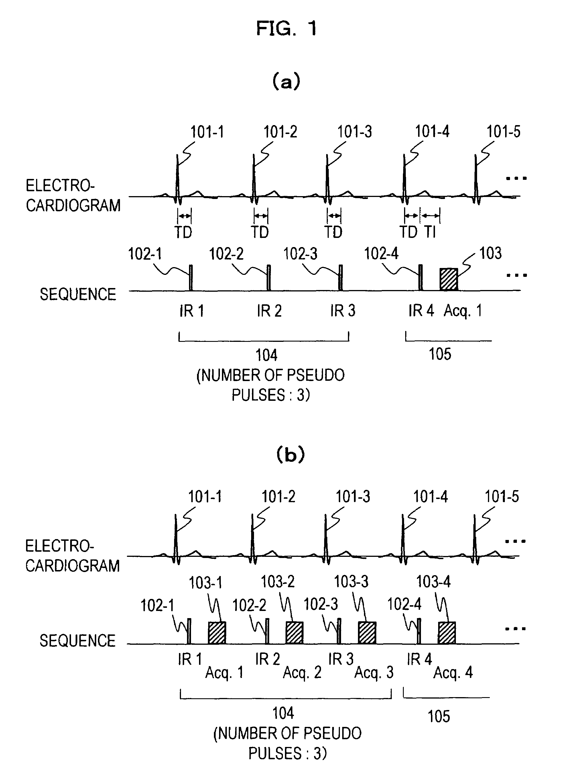
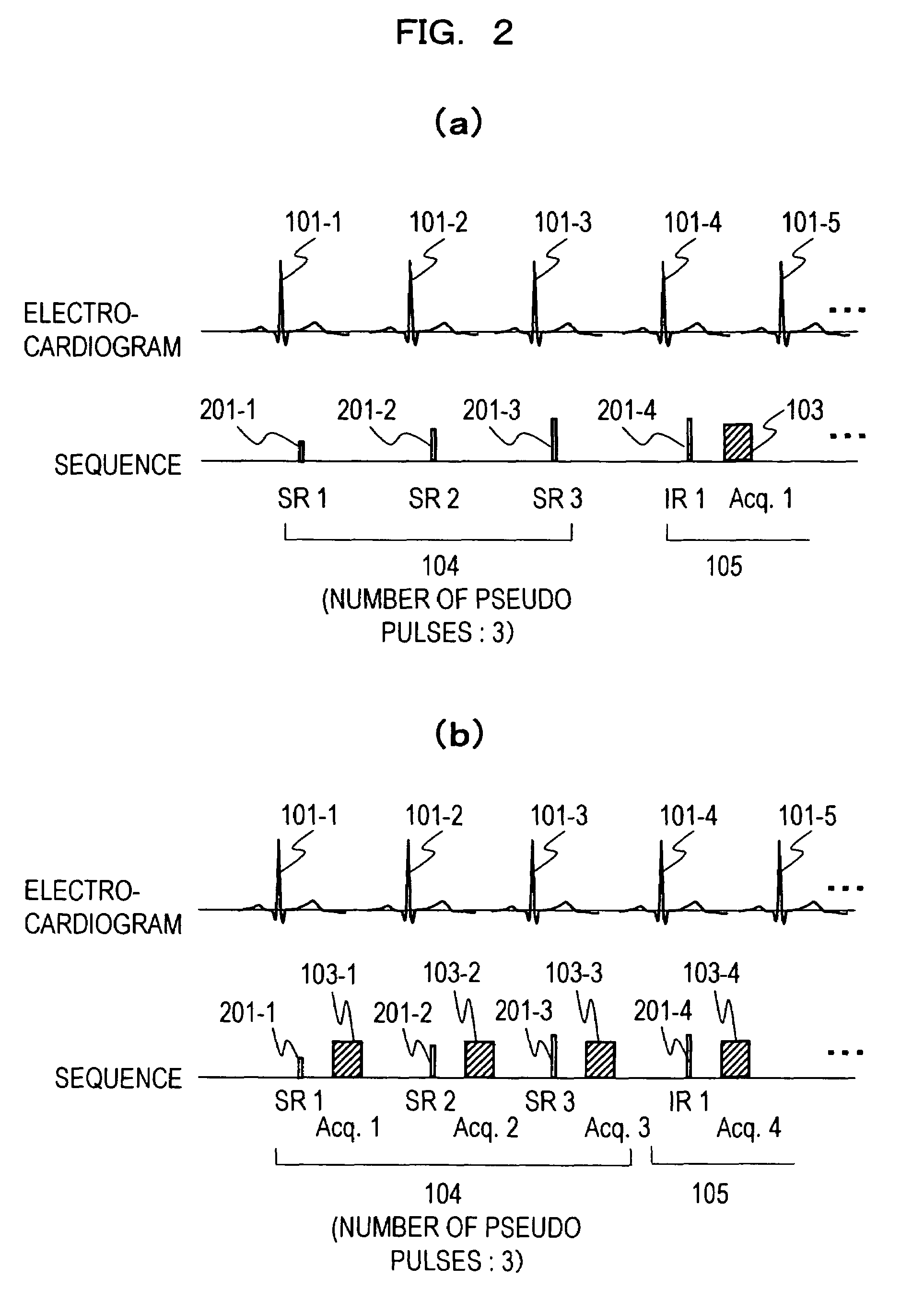
[0047]A first embodiment of the present invention will now be explained. This embodiment is in a form to implement, at a start of imaging, a first pulse sequence to regulate the longitudinal-magnetization in a region including a desired imaging region of a subject prior to a second pulse sequence to measure an echo signal from the desired imaging region, where to take an image by use of a sequence for applying a pre-saturation pulse.

[0048]The present embodiment is explained of its content with an exemplification that the embodiment is applied for delayed contrast-enhanced imaging.

[0049]Based on the sequence shown in FIG. 4, explained first is the outline of a delayed contrast-enhanced imaging to be implemented by use of the MRI apparatus, noted before. This sequence is an example of a second pulse sequence, which, from now on, is referred to as the main measuring sequence. However, the invention is not limited to the main measuring sequence.

[0050]At first, a T1-reduced contrast agen...

second embodiment

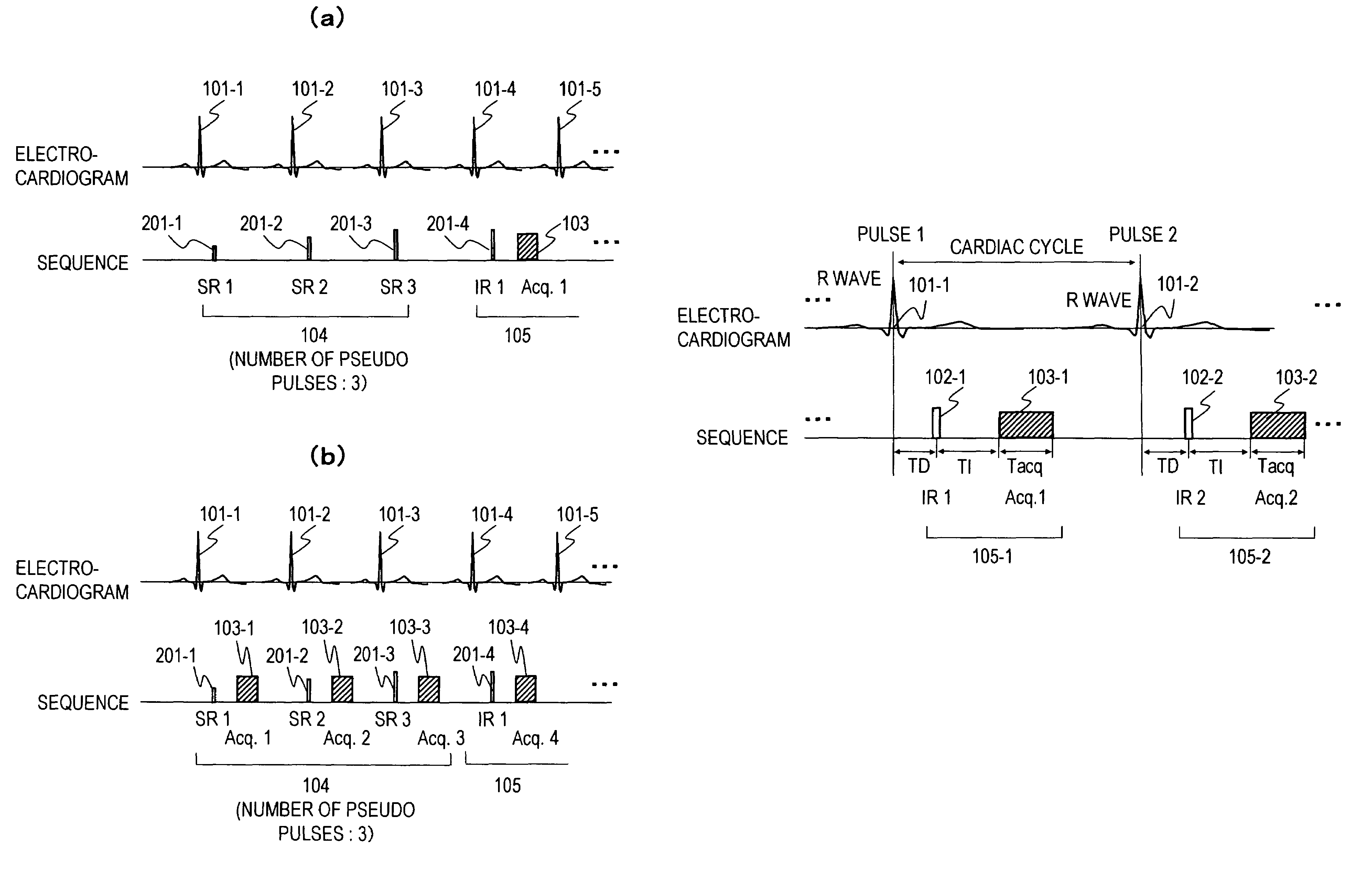
[0072]A second embodiment of the invention is explained. The first embodiment was in the form to reduce the intensity variation of echo signals, constituting a cause of artifact, by applying the first pulse sequence at a start of imaging. However, where there is a change of the period of periodical physical movement of the subject, there is encountered the intensity variation of echo signals. For this reason, the second embodiment is in a form to insert and execute a first pulse sequence, that regulates the longitudinal-magnetization in a region including a desired imaging region of the subject, into a second pulse sequence, that measures an echo signal from the desired imaging region, immediately after a period change in the subject periodic physical movement of the subject.

[0073]Based on FIG. 3, explanation is made on one example of the present embodiment assuming an irregular pulse, as an example there is a change in periodic physical movement. Here, it is possible to determine w...

third embodiment

[0080]A third embodiment of the invention is explained. This embodiment is in a form that, in such a case that a desired imaging region is temporarily moved due to a physical movement of the subject, when the desired imaging region comes back to the former position, a first pulse sequence, for regulating the longitudinal-magnetization in a region including the desired imaging region, is inserted and performed in a second pulse sequence for measuring an echo signal of from the desired imaging region.

[0081]Based on FIGS. 6 and 7, explanation is made on one example of the present embodiment assuming respiratory movement, as an example that a desired imaging region changes in position due to a periodic physical movement.

[0082]In the case there is a difficulty for the subject to stop his / her breath, imaging is desired to perform with free respiration. However, with free respiration, the heart moves in position associatively with vertical movement of the diaphragm. For this reason, there ...


PUM


Abstract

When performing imaging in synchronization with a biological movement of an examinee by using a pulse sequence applying a pre-saturation pulse, it is possible to reduce irregularities of echo signal intensity and artifact on the image generated by the irregularities. Especially, it is possible to prevent artifact attributed to blood in the ventricle when performing delay contrast imaging. For this, before measuring the echo signal, an IR pulse or the like for adjusting magnetization to a desired state is applied so as to suppress irregularities of the echo signal intensity and prevent artifact.

Description

TECHNICAL FIELD[0001]The present invention relates to a magnetic resonance imaging method and apparatus for taking an image of a desired imaging region of a subject, and more particularly to an art adapted to reduce the intensity variation of echo signals when performing an imaging synchronously with physical movement of the subject by use of a pulse sequence for applying a pre-saturation pulse.BACKGROUND ART[0002]In the magnetic resonance imager, it is a practice to perform a delayed contrast-enhanced imaging that extracts a heart muscle in the form of a high signal region based on T1-enhanced imaging through utilization of the property a contrast agent, such as Gd-DTPA, is to aggregate on the heart muscle in the state of necrosis / infarction.[0003]The application of a magnetic field in delayed contrast-enhanced imaging (pulse sequence, hereinafter referred merely to as sequence) is generally based on a procedure as per the following. Namely, after a wait time TD (first wait time) f...

Claims


Application Information

Patent Timeline
Patent Type & Authority Patents(United States)
IPC IPC(8): A61B5/055G01R33/563G01R33/567
CPCG01R33/5601G01R33/5602G01R33/563G01R33/5635G01R33/565G01R33/5673G01R33/5614G01R33/56509G01R33/5676
Inventor ITAGAKI, HIROYUKIGOTO, TOMOHIROYATSUI, YUMIKOTAKAHASHI, TETSUHIKO
Owner HITACHI LTD
Why Eureka
Try Eureka