
Product clamp for food slicing machine

a technology for clamping products and food products, which is applied in the direction of metal sawing devices, metal sawing apparatuses, manufacturing tools, etc., can solve the problems of small inconsistencies in food slices, inability to properly fit logs, and undesirable movement, so as to reduce or prevent the movement of food products and avoid damage to food products.

Active Publication Date: 2010-03-30
J E GROTE
View PDF15 Cites 1 Cited by
  • Summary
  • Abstract
  • Description
  • Claims
  • Application Information

AI Technical Summary

Benefits of technology

"The invention is a machine for slicing food products that has a holder with a sidewall that defines an elongated barrel for holding the food product. The holder is driven by a rotating shaft to move the food product through a blade during a portion of its stroke. The machine also has a drive rod with a plunger that is linked to a plate that is pivotably mounted to the holder. The plunger has a product end that extends through an aperture in the holder to clamp the food product against the holder sidewall during the slicing portion of the holder's stroke. The machine also has springs that apply a force to hold the food product in place without damaging it. The invention allows for consistent slices and allows the food product to fall towards the blade end of the holder under the influence of gravity."

Problems solved by technology

It is common for there to be small inconsistencies in food slices due to the movement of the food log in the product holder during cutting.
This movement is undesirable due to the variations in slices that result.
Alternatively, if the product holder is the same width of the food log, two problems arise.
First, variations in food log dimensions will cause some logs to fit correctly and others to fit incorrectly within the barrel.
Second, if there is no space between the food log and the product holder sidewall, loading of the food log will be difficult due to the lack of any tolerance for misalignment of the log with the barrel of the holder, and friction between the food log and the walls of the barrel may prevent the food log from feeding properly due to the force of gravity.

Method used


Image

  • Product clamp for food slicing machine
  • Product clamp for food slicing machine
  • Product clamp for food slicing machine

Examples


Embodiment Construction

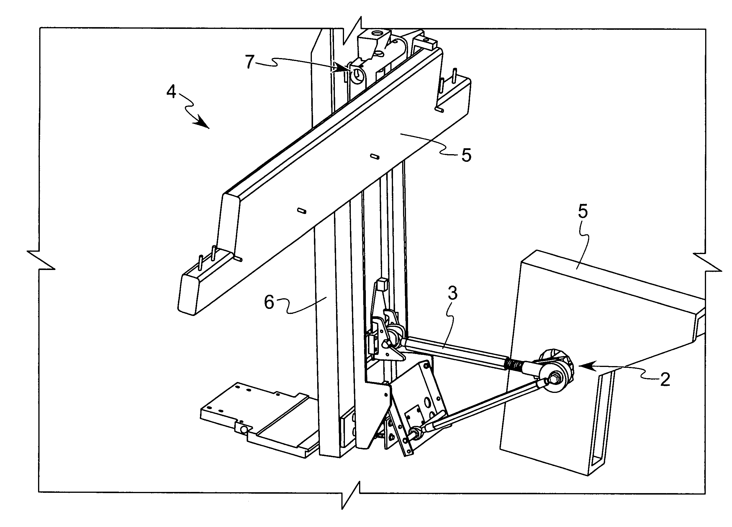
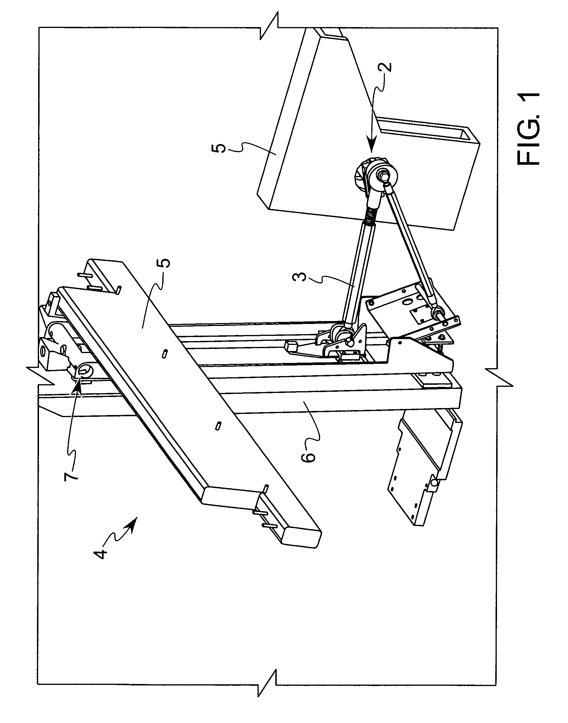
[0027]The present invention is illustrated in FIG. 1 on a conventional food slicing machine 4. The machine 4 has a frame 5, which is made up of a plurality of members, only a few of which are illustrated, mounted together and resting upon a work surface, typically a food processing plant floor. Other parts of the machine 4 mount to the frame 5, and are supported by the frame 5. For example, a product holder 6 is pivotably mounted to the frame 5 at a pivot 7, and pivots its lower end through a path adjacent the blade 8 (see FIG. 14). The blade 8 is preferably a conventional band blade that is driven rapidly through a blade guide by a pulley system as described in the patents incorporated by reference herein.

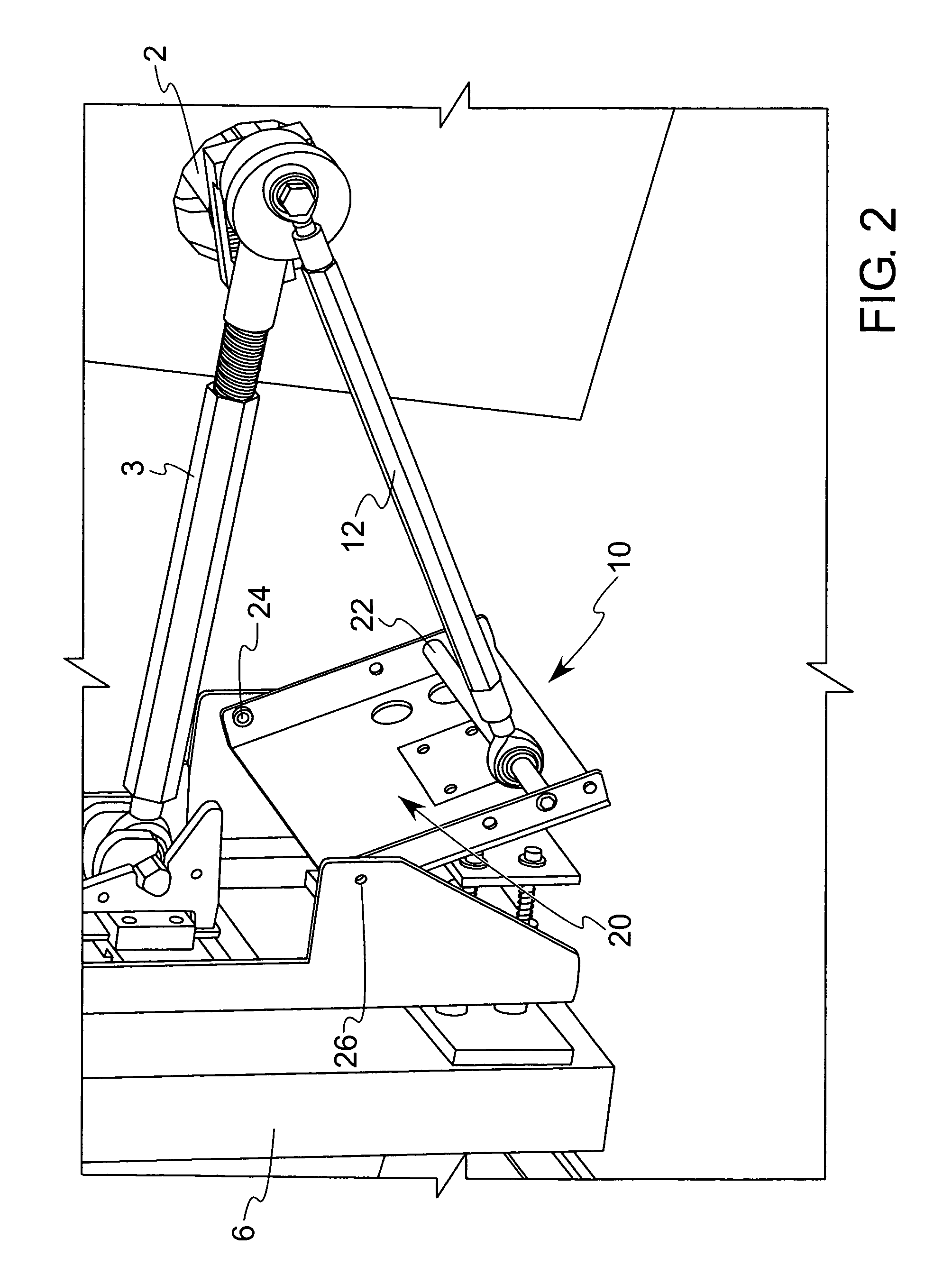
[0028]The product holder 6 is reciprocatingly driven about the pivot 7 by a driveshaft 2 that rotates at a desired slicing speed, which can be low or high speed, about an axis of rotation that is coaxial with the axis of the shaft 2. The connecting rod 3 has a rotary connection to...


PUM

PropertyMeasurementUnit
forceaaaaaaaaaa
shapeaaaaaaaaaa
elongated shapeaaaaaaaaaa

Abstract

A clamping mechanism for a food slicing machine having a product holder that is driven cyclically through a food slicing blade along an arcuate or linear path. The clamping mechanism is driven by the drive means that drives the product holder, thereby assuring the timing of the clamping during the cutting portion of the stroke. A drive rod extends from the drive means, which can be a driveshaft, and extends to a plate that is pivotably mounted to the product holder. The plate pushes plungers through the sidewall of the holder to seat against and clamp the food product against the sidewall of the holder.

Description

BACKGROUND OF THE INVENTION[0001]1. Field of the Invention[0002]This invention relates generally to a food product slicing machine, and more particularly to an apparatus for cyclically clamping and releasing a food product in a moving product holder.[0003]2. Description of the Related Art[0004]Conventional food product slicing machines, such as the machine disclosed in U.S. Pat. No. 3,760,715 to Grote et al. (which is incorporated herein by reference), reciprocatingly displace food logs along a path through a slicing blade for removing thin slices of the food product during each stroke. Whereas the Grote et al. patent teaches to displace food products through a linear path, other food slicing machines displace food products through an arcuate path. Such a machine is shown in U.S. Pat. No. 4,436,012 to Hochanadel, which is also incorporated herein by reference. In the Hochanadel machine, a food product holder is reciprocatingly pivoted about an axle to swing a food product held there...

Claims


Application Information

Patent Timeline
Patent Type & Authority Patents(United States)
IPC IPC(8): B26D11/00B23D19/00B23D45/00B26D5/20B26D7/06B27B5/18
CPCB26D7/04B26D7/0641Y10T83/4594Y10T83/7487Y10T83/6492Y10T83/023Y10T83/4582Y10T83/4645Y10T83/654B26D7/02
Inventor MATHUES, THOMAS P.LOCASCIO, WILLIAM J.
Owner J E GROTE
Learn More