Fire protection device for a zone

a fire protection device and a zone technology, applied in fireproofing, extraordinary structures, building components, etc., can solve the problems of fire in buildings and the inability to protect all houses, and achieve the effect of better thermal isolation

Active Publication Date: 2010-03-30
KLEFF WOLFGANG
View PDF11 Cites 15 Cited by
  • Summary
  • Abstract
  • Description
  • Claims
  • Application Information

AI Technical Summary

Benefits of technology

[0015]Loops may also be arranged on the upper and lower faces of the surface sections to enable people to climb up surface sections that are already secured. Spacers may be located in the surface sections to prevent individual surface sections from expanding, caused for example by the individual plies separating from each other.
[0016]In a further refinement of the invention, it is provided that the plies of the covering are filled with a non-flammable material. This non-flammable material insulates the two opposing sides of the surface sections from each other. The peripheral edges of the covering may be formed by closed seams to prevent the non-flammable material from falling out of the surface sections. Rivets may also be provided to further reinforce the multiple-ply covering.
[0017]Finally, a refinement of the invention provides that a protected zone is formed by the covering itself. Particularly in the case of multiple surface sections, a tent-like structure may be created that provides protection particularly for people. In this context, surface sections may be placed on top of each other in several layers for better thermal isolation.

Problems solved by technology

Fires in buildings are often caused by technical faults inside the building.
However, if entire streets are threatened, as may happen in a forest fire or wildfire, for example, it is often impossible to protect all of the houses by deploying the fire service because their resources are insufficient.

Method used


Image

  • Fire protection device for a zone
  • Fire protection device for a zone
  • Fire protection device for a zone

Examples


Embodiment Construction

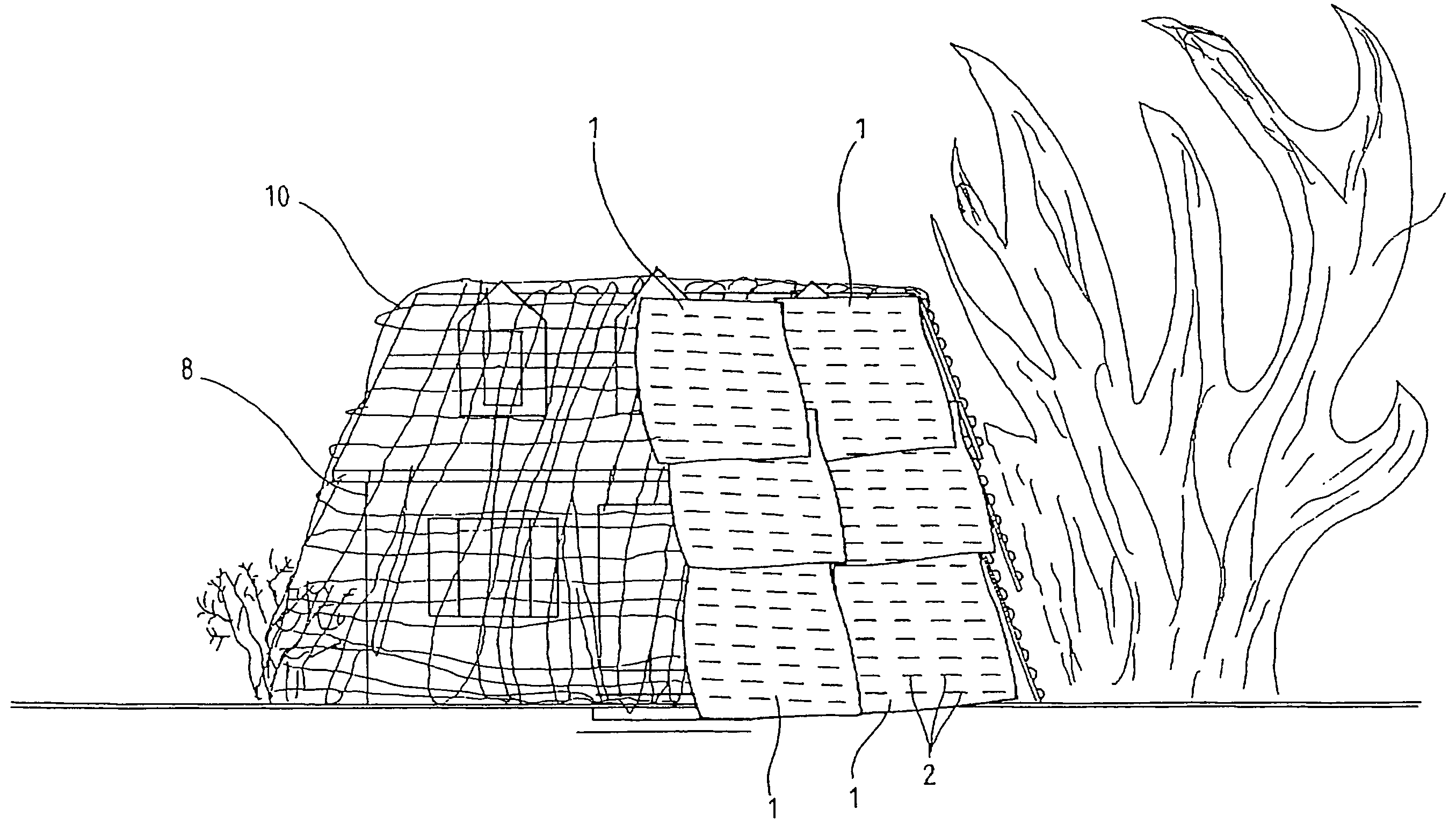
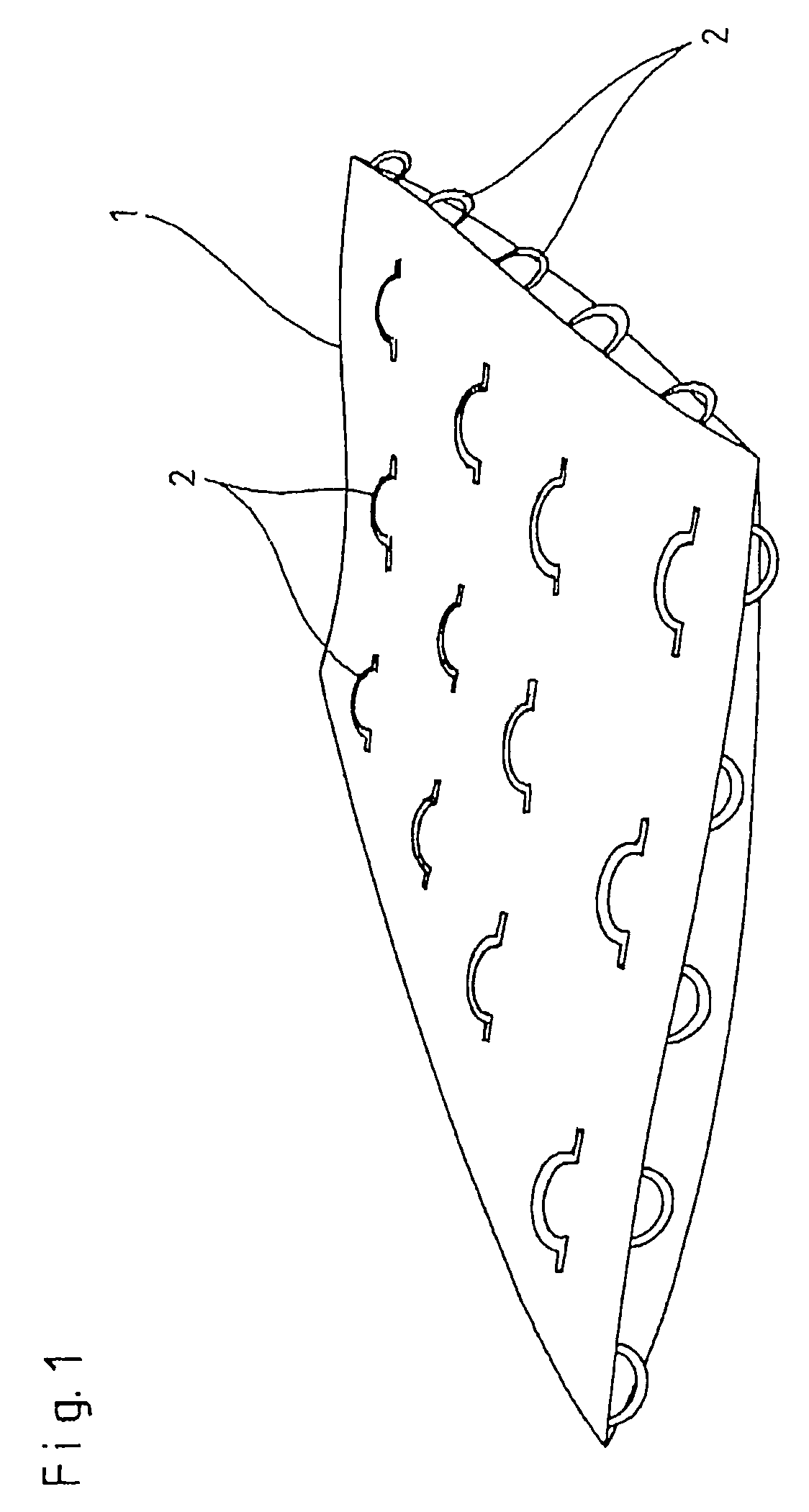
[0024]The fire protection device shown in the figures consists of individual surface sections 1. Each surface section 1 has the form of a mat, and is constructed with multiple plies. Connecting and climbing means designed as loops 2 are located on the edges of surface section 1 and on the upper face of surface section 1.

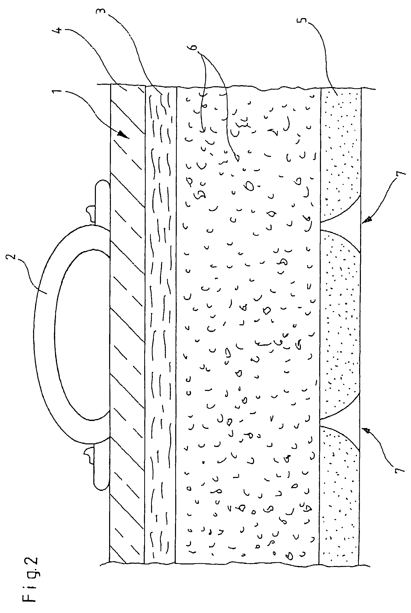
[0025]FIG. 2 shows loops 2 on the upper face of surface section 1. The uppermost ply of surface section 1 is formed by a glass fibre layer 3 that has an aluminum-coated surface 4. The bottom ply of surface section 1 is formed by a fire-resistant material 5, for example a layer of mineral fibre.

[0026]The cavity between glass fibre layer 3 and material 5 is filled with padding 6 of fire-resistant material. Perforations 7 are created in material ply 5 of the surface section 1 to be filled with padding 6.

[0027]When a fire protection device according to the invention is secured to a building 8, the procedure is performed in steps as shown in FIGS. 3a to 3d. First, a suppo...


PUM

PropertyMeasurementUnit
support structureaaaaaaaaaa
non-flammableaaaaaaaaaa
toughnessaaaaaaaaaa

Abstract

In a fire protection device for protecting a zone in which a building and/or people is/are located, it is suggested that it be constructed from fire-resistant material and be larger than the spatial dimensions of the zone to be protected. This fire protection device particularly enables the owner or resident of a building to protect the building from the threat of an external fire even when the fire service is not present.

Description

CROSS REFERENCE TO RELATED APPLICATIONS[0001]Applicant claims priority under 35 U.S.C. §119 of German Application No. 10 2006 030 627.9 filed Jul. 3, 2006.BACKGROUND OF THE INVENTION[0002]1. Field of the Invention[0003]The invention relates to a fire protection device for a zone requiring protection, in which a building or people is / are located.[0004]2. Description of the Related Art[0005]Fires in buildings are often caused by technical faults inside the building. Many fire protection devices have already been suggested for such circumstances, to prevent fires from occurring and / or to combat them when they do occur.[0006]If a fire threatens a building from outside, for example if the building is at risk from a fire in a neighboring house or an approaching forest fire, the fire protection for the building essentially consists of action by the fire service. However, if entire streets are threatened, as may happen in a forest fire or wildfire, for example, it is often impossible to pro...

Claims


Application Information

Patent Timeline
Patent Type & Authority Patents(United States)
IPC IPC(8): A62C8/06A62C3/00A62C99/00
CPCA62C3/0257A62C8/08B32B17/02B32B17/067B32B19/06E04B1/94E04B1/941E04H9/04A62C8/06Y10S52/12
Inventor KLEFF, WOLFGANG
Owner KLEFF WOLFGANG
Why Eureka
Try Eureka