Methods and apparatus for controlled-angle wafer positioning

a technology of controlled angle and positioning method, which is applied in the direction of electrolysis components, transportation and packaging, electrolysis processes, etc., can solve the problems of difficult removal from the wafer surface, difficulty in removing metal films from the wafer, and difficulty in gas entrapment and subsequent defect formation

Inactive Publication Date: 2010-03-30
NOVELLUS SYSTEMS
View PDF43 Cites 26 Cited by
  • Summary
  • Abstract
  • Description
  • Claims
  • Application Information

AI Technical Summary

Benefits of technology

[0013]The present invention provides methods and apparatus for controlling the orientation of a wafer with respect to the surface of an electrolyte during an electroplating process. A wafer is delivered to an electrolyte bath along a trajectory normal to the surface of the electrolyte. Along this trajectory, the wafer is angled before entry into the electrolyte for angled immersion. A wafer can be plated in an angled orientation or not, depending on what is optimal for a given situation. Also, in some designs, the wafer's orientation can be adjusted actively during immersion or during electroplating. Active angle adjustment refers to changing the angle of the wafer at any time during positioning or plating. This provides flexibility in various plating scenarios.
[0021]As mentioned, the invention finds particular use in the context of copper electroplating. In modern damascene processing, conditions have to be increasingly stringent for optimal plating quality and throughput. The invention provides plating environments with less possibility for defects caused by bubbles and multiple wetting fronts.

Problems solved by technology

A continuing issue in modern VLSI wafer electroplate processing is quality of the deposited metal film.
Air bubbles trapped on the plating surface of a wafer can cause many problems.
They are difficult to remove from the wafer surface because the plating cell has no intrinsic mechanism for driving the bubbles around the wafer edges, the only path off the wafer surface.
This also helps to dislodge bubbles through centrifugal force, but many of the smaller bubbles are tenacious in their attachment to the wafer.
Therefore, while horizontal wafer orientation (especially coupled with a vertical immersion trajectory) has numerous advantages from a hardware configuration and throughput standpoint, it leads to technically challenging issues associated with gas entrapment and consequent defect formation.
Unfortunately, the radial non-uniformity of the forced convection of such systems can result in non-uniform plating profiles.
Another problem associated with vertical immersion of a horizontally oriented wafer is multiple wetting fronts.
Where individual wetting fronts converge, bubbles may be trapped.
Also, defects in the finished plating layer can be propagated from microscopic unwetted regions formed along convergence lines of multiple wetting fronts.

Method used


Image

  • Methods and apparatus for controlled-angle wafer positioning
  • Methods and apparatus for controlled-angle wafer positioning
  • Methods and apparatus for controlled-angle wafer positioning

Examples


Embodiment Construction

[0035]In the following detailed description of the present invention, a few specific embodiments are set forth in order to provide a thorough understanding of the invention. However, as will be apparent to those skilled in the art, the present invention may be practiced without these specific details or by using alternate elements or processes. In some descriptions herein, well-known processes, procedures, and components have not been described in detail so as not to unnecessarily obscure aspects of the present invention.

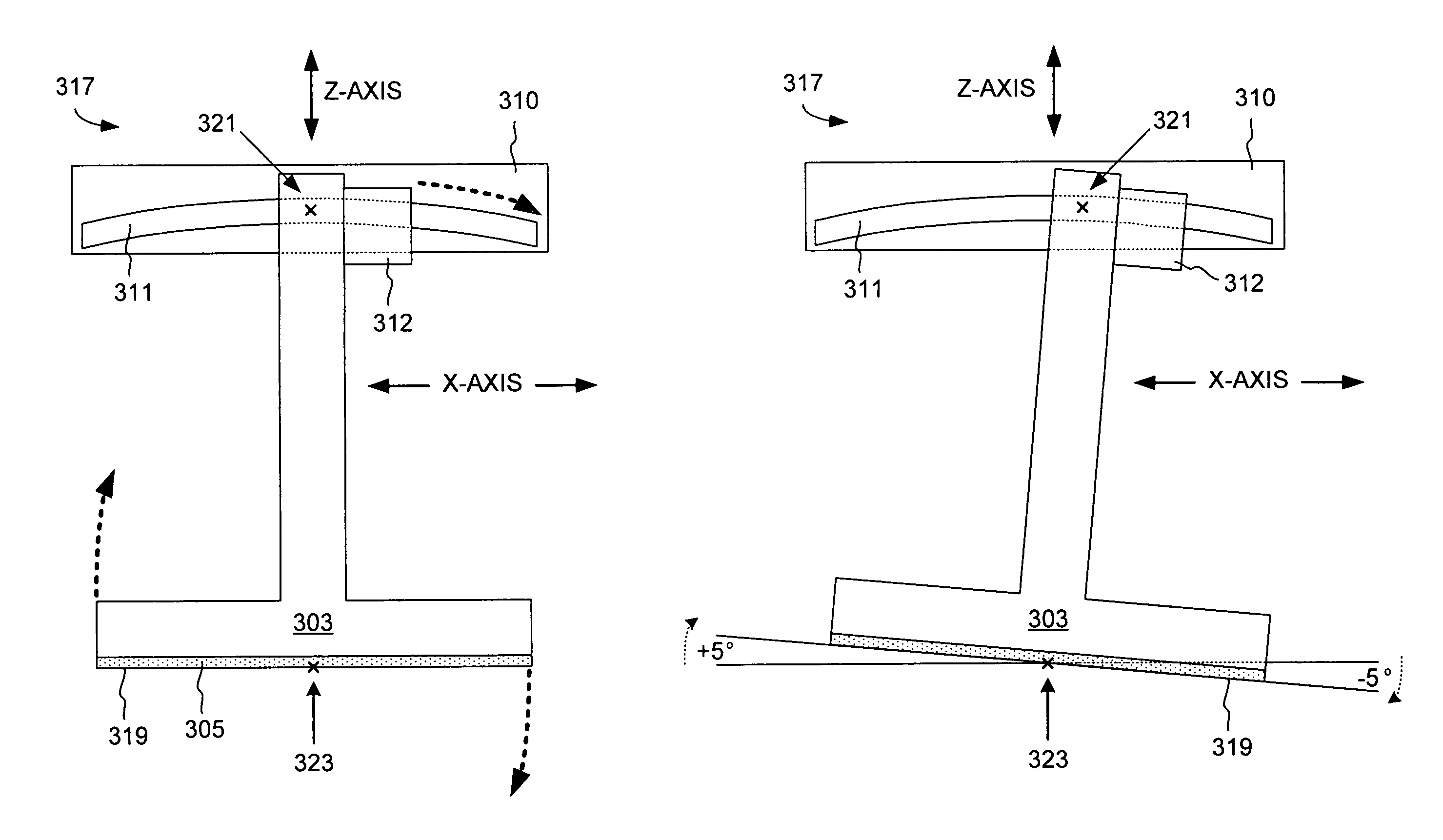
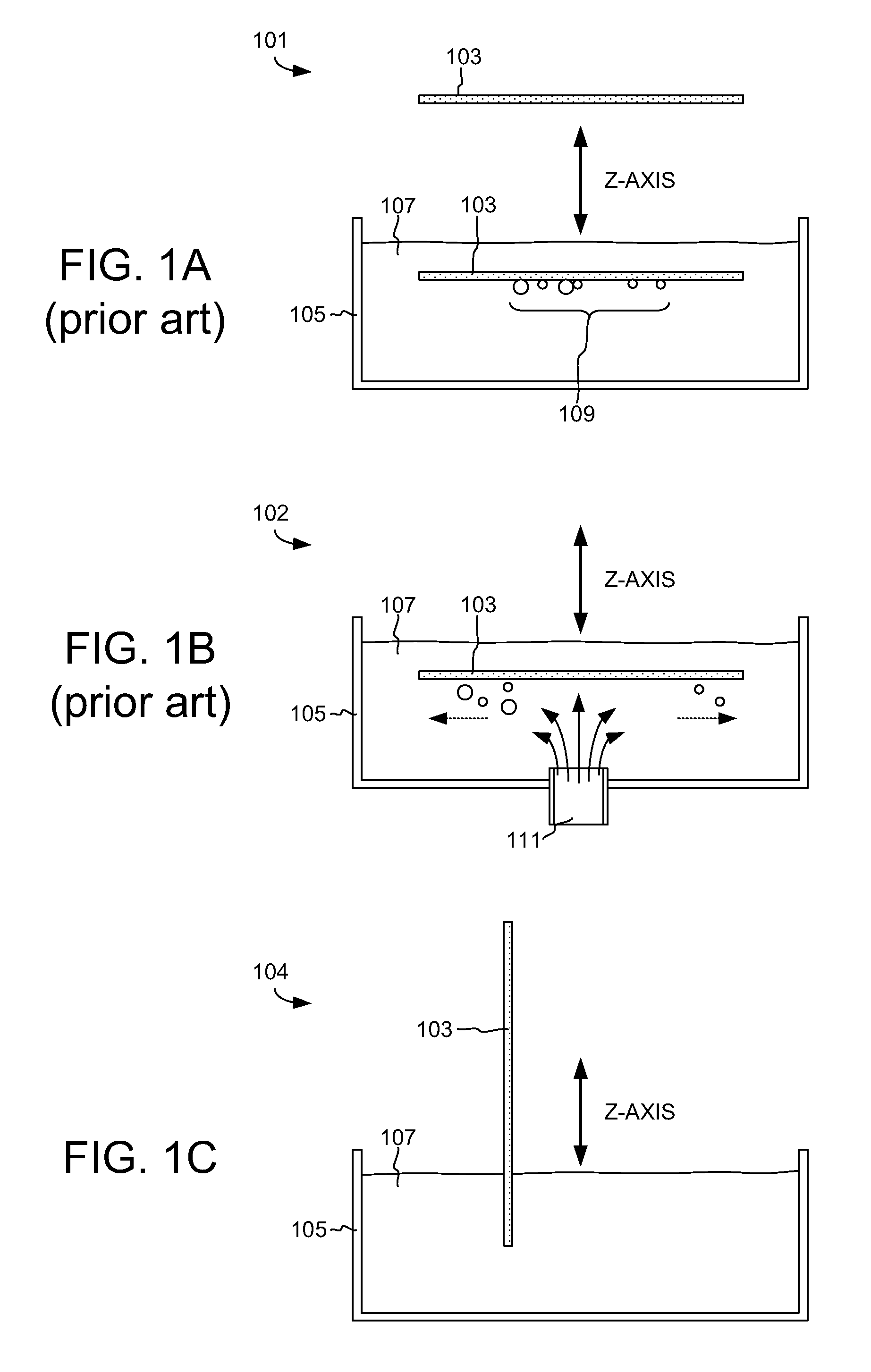
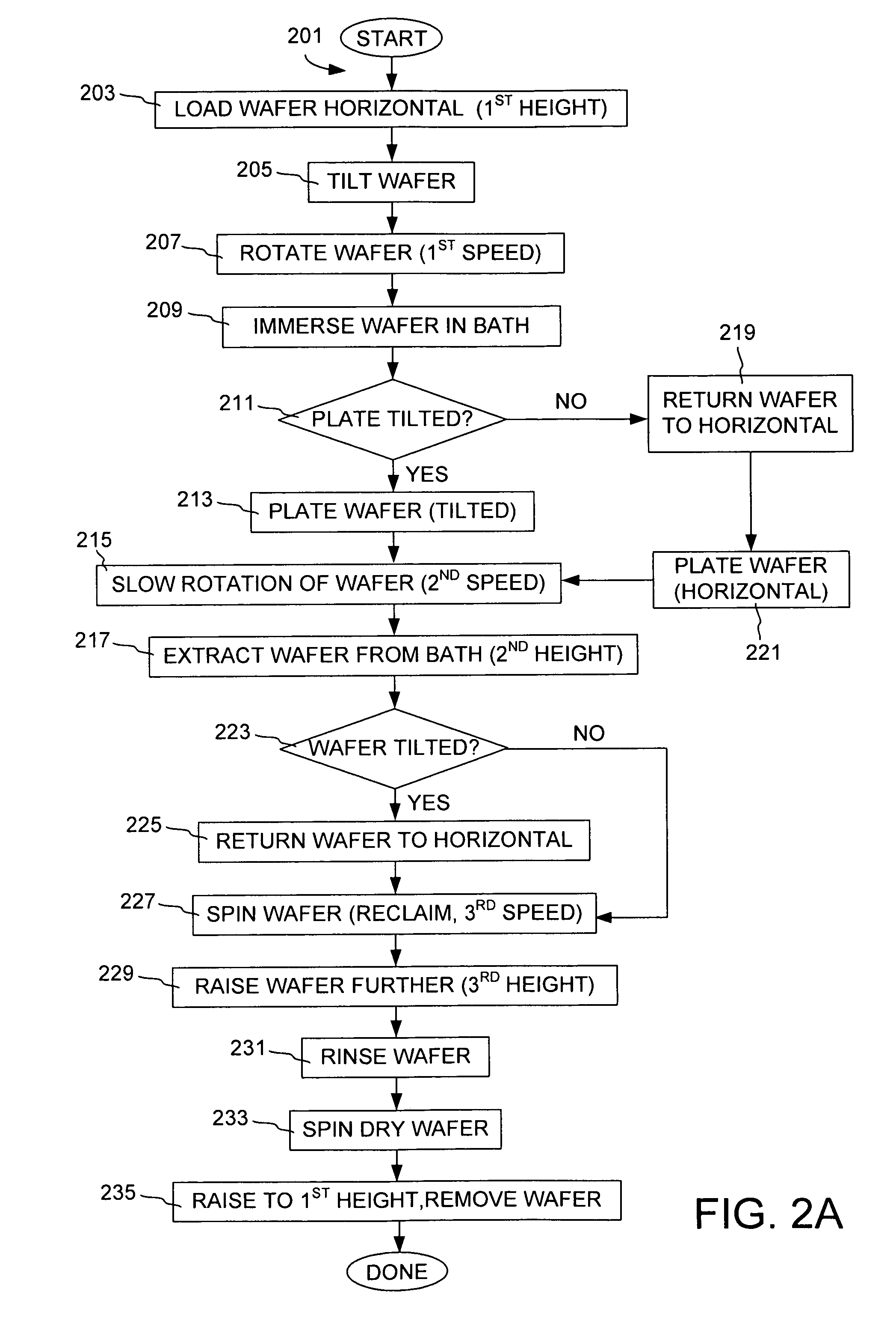
[0036]A central aspect of the invention pertains to methods of positioning a wafer relative to a plane defined by the surface of an electrolyte in an electroplating apparatus. Generally, the positioning involves two operations: (1) moving the wafer into or out of the electrolyte along a trajectory substantially normal to the plane defined by the surface of the electrolyte, and (2) adjusting the angle defined by the relative position of a planar plating surface of th...


PUM

PropertyMeasurementUnit
speedaaaaaaaaaa
speedaaaaaaaaaa
angleaaaaaaaaaa

Abstract

The orientation of a wafer with respect to the surface of an electrolyte is controlled during an electroplating process. The wafer is delivered to an electrolyte bath along a trajectory normal to the surface of the electrolyte. Along this trajectory, the wafer is angled before entry into the electrolyte for angled immersion. A wafer can be plated in an angled orientation or not, depending on what is optimal for a given situation. Also, in some designs, the wafer's orientation can be adjusted actively during immersion or during electroplating, providing flexibility in various electroplating scenarios.

Description

CROSS-REFERENCE TO RELATED APPLICATIONS[0001]This application is a Divisional of U.S. patent application Ser. No. 10 / 379,858, by Reid et al., titled, “Methods and Apparatus for Controlled-Angle Wafer Positioning,” (now U.S. Pat. No. 7,097,410, Issued on Aug. 29, 2006) and filed on Mar. 4, 2003 which in turn is a Divisional of U.S. patent application Ser. No. 09 / 872,341, filed May 31, 2001 by Reid et al., titled, “Methods and Apparatus for Controlled-Angle Wafer Immersion,” (now U.S. Pat. No. 6,551,487, Issued on Apr. 22, 2003). Each of these applications is incorporated herein by reference for all purposes.[0002]This application is related to the following US Patent Applications: U.S. patent application Ser. No. 09 / 927,741, naming Jonathan Reid, Steven Mayer, Marshall Stowell, and Evan Patton as inventors, titled “Improved Clamshell Apparatus for Electrochemically Treating Wafers,” and filed Aug. 10, 2001; U.S. patent application Ser. No. 09 / 872,340, naming Evan Patton, David Smith,...

Claims


Application Information

Patent Timeline
Patent Type & Authority Patents(United States)
IPC IPC(8): C25D17/00C25D7/12H01L21/288
CPCH01L21/2885C25D17/001Y10S414/135Y10S414/136
Inventor REID, JONATHAN D.MAYER, STEVEN T.VARADARAJAN, SESHASAYEESMITH, DAVID C.PATTON, EVAN E.KALAKKAD, DINESH S.LIND, GARYHILL, RICHARD S.
Owner NOVELLUS SYSTEMS
Why Eureka
Try Eureka