Slot seal

a technology of slot seal and slot ring, which is applied in the direction of windings, electrical apparatus, dynamo-electric machines, etc., can solve the problems of insufficient insulation of conductor arrangement, short circuits, and inability to optimally fix the conductor arrangement, so as to optimize the absorption capacity of impregnation resin

Inactive Publication Date: 2010-03-30
SIEMENS AG
View PDF27 Cites 7 Cited by
  • Summary
  • Abstract
  • Description
  • Claims
  • Application Information

AI Technical Summary

Benefits of technology

[0016]In order to optimize the absorption capability for impregnation resin, the slot seal has at least one opening on the convex curve or the cover. If there were a large number of small openings, it would thus advantageously be possible for impregnation resin to enter the slot seal, and to fix it. Furthermore, this also allows the impregnation resin to penetrate through the slot seal and to fix the conductor arrangement. Furthermore, the springing effect of the convex curve can be advantageously influenced by means of at least one opening on the convex curve. When the slot seal according to the invention is used in an electrical machine, all of the abovementioned advantages can be achieved. The slot seals advantageously have means for holding and / or fixing a slot seal. These means may be slits in the side walls of the slot or else tabs on both sides of the slot opening.

Problems solved by technology

However, this has the disadvantage that there is generally an intermediate space between the slot seal and the inserted conductor arrangement, as a result of which the conductor arrangement is not optimally fixed.
In consequence, the conductor arrangement can move in the slot during operation or transport of the electrical machine, as a result of which the insulation of the conductor arrangement may be damaged by being cut through, and short circuits may occur.

Method used


Image

  • Slot seal
  • Slot seal

Examples


Embodiment Construction

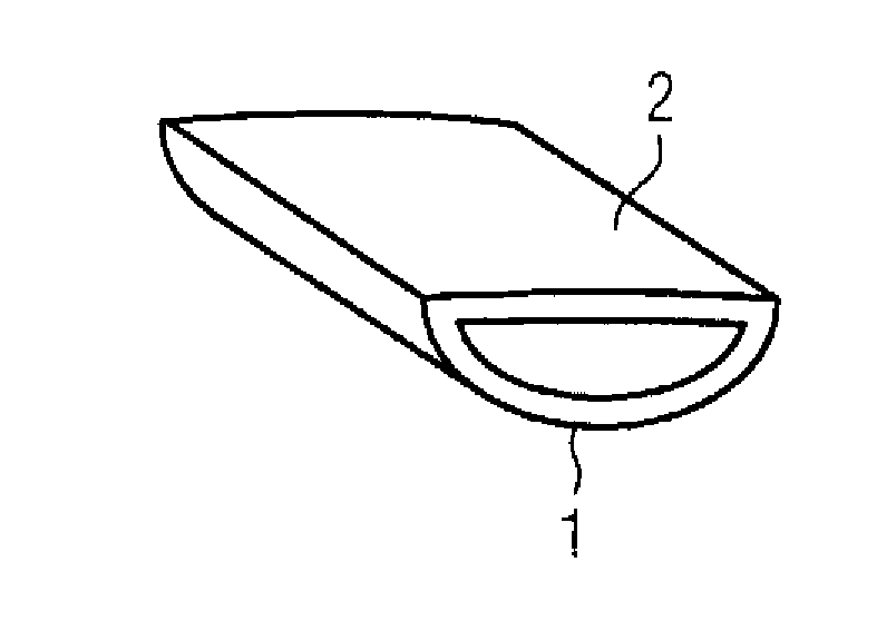
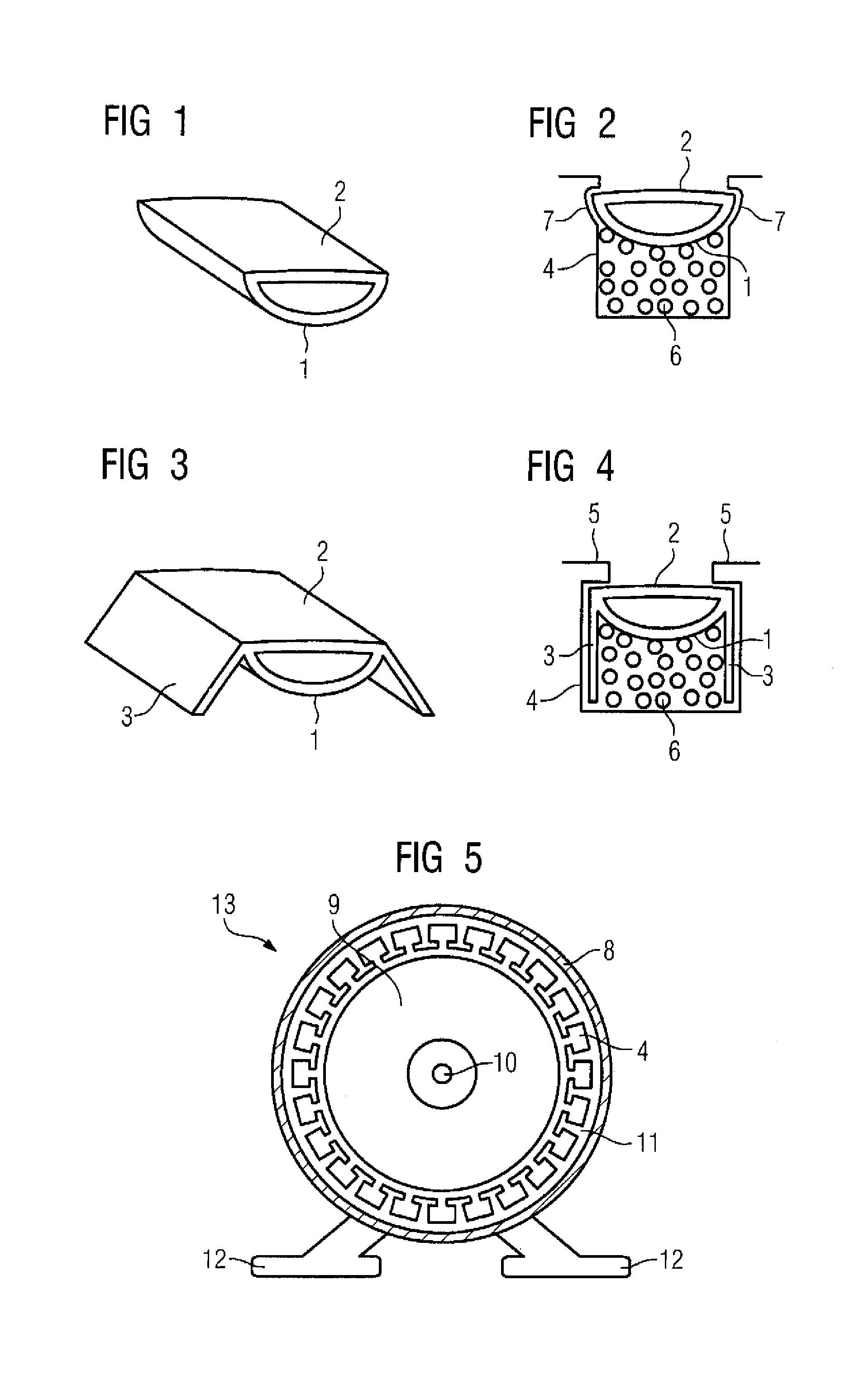
[0023]FIG. 1 shows a slot seal according to the invention in the form of a slot seal wedge. In this example, this comprises a main body in the form of a convex curve 1 and a cover 2, which firmly connects the two ends of the convex curve 1 to one another. When the slot seal wedge is inserted into the slot, then the slot seal wedge matches itself to the conductor arrangement which has been inserted in the slot, by being deformed. The conductor arrangement is fixed firmly in the slot by the springing affect of the convex curve 1. By way of example, the cover 2 is used to make the slot seal wedge robust.

[0024]FIG. 2 shows a slot 4 with a slot seal wedge according to the invention. The grooves 7 in the slot 4 in this case guide and fix the slot seal wedge. The springing effect of the convex curve 1 in this case ensures that the conductor arrangement 6 is fixed securely.

[0025]In order to optimize the absorption capability for impregnation resin, the slot seal wedge may have at least one ...


PUM


Abstract

The invention relates to a slot seal for an electric machine (13) comprising at least one slot (4) provided with a slot opening for arranging an electric conductor arrangement (6), wherein said slot sealing comprises, on the face thereof oriented towards the conductor arrangement (6), at least one bulge (1) which is oriented to the electric conductor arrangement (6), extends along at least one part of the slot seal length and is selected in such a way that it is elastic or at least deformable and the ends thereof are fixedly interconnected, at least partially, by a cover (2).

Description

BACKGROUND OF THE INVENTION[0001]The invention relates to a slot seal for an electrical machine which contains at least one slot with a slot opening for holding an electrical conductor arrangement, wherein the slot seal can be inserted in order to seal the slot opening.[0002]Slot seals are used in electrical machines, in order to seal slots in the rotor and / or the stator. Conductor arrangements are inserted in the slots and ensure the operation of the electrical machine. The conductor arrangements are formed by winding systems composed of insulated wires. The slot seals ensure that the winding system cannot fall out and become mechanically damaged during assembly of the motor.[0003]The document DE 1 288 186 A discloses one way in which a slot seal can be designed. In this document, the slot seal is in the form of a rigid slot seal wedge.[0004]However, this has the disadvantage that there is generally an intermediate space between the slot seal and the inserted conductor arrangement,...

Claims


Application Information

Patent Timeline
Patent Type & Authority Patents(United States)
IPC IPC(8): H02K3/48
CPCH02K3/487H02K3/493H02K15/0056
Inventor KLAUSSNER, BERNHARD
Owner SIEMENS AG
Why Eureka
Try Eureka