Micromachined, piezoelectric vibration-induced energy harvesting device and its fabrication

a micro-machined, piezoelectric technology, applied in piezoelectric/electrostrictive/magnetostrictive devices, piezoelectric/electrostriction/magnetostriction machines, electrical apparatus, etc., can solve the problem of finite lifetime limitation of power sources, and achieve the effect of reducing power requirements to the range of microwatts

Inactive Publication Date: 2010-03-30
HONEYWELL INT INC
View PDF22 Cites 37 Cited by
  • Summary
  • Abstract
  • Description
  • Claims
  • Application Information

AI Technical Summary

Benefits of technology

[0007]In order to fulfill future power supply requirements for wireless, contactless and potentially implantable systems, the present inventor herein teaches a MEMS-based piezoelectric-type, vibration-induced energy-harvesting device. To eliminate the need of batteries, harvesting energy from ambient power sources is a promising solution. Advances in low power VLSI design, along with the low duty cycles of miniaturized wireless sensors have reduced power requirements to the range of microwatts so that power supplied by energy harvesting could be a viable alternative.

Problems solved by technology

The problem associated with the concept of a wireless network, however, lies with determining how to supply power to contactless, embedded sensors.
Batteries are automatically thought to be a solution for providing power to remote device, but such power sources are limited by their finite lifetime.
In addition, sensor nodes tend to be portable and integrated with multi-functions, therefore, limited power issues, small size and integration capabilities pose additional problems in front of the effective implementation of a promising wireless sensor network.

Method used


Image

  • Micromachined, piezoelectric vibration-induced energy harvesting device and its fabrication
  • Micromachined, piezoelectric vibration-induced energy harvesting device and its fabrication
  • Micromachined, piezoelectric vibration-induced energy harvesting device and its fabrication

Examples


Embodiment Construction

[0014]The particular values and configurations discussed in these non-limiting examples can be varied and are cited merely to illustrate at least one embodiment and are not intended to limit the scope of the invention.

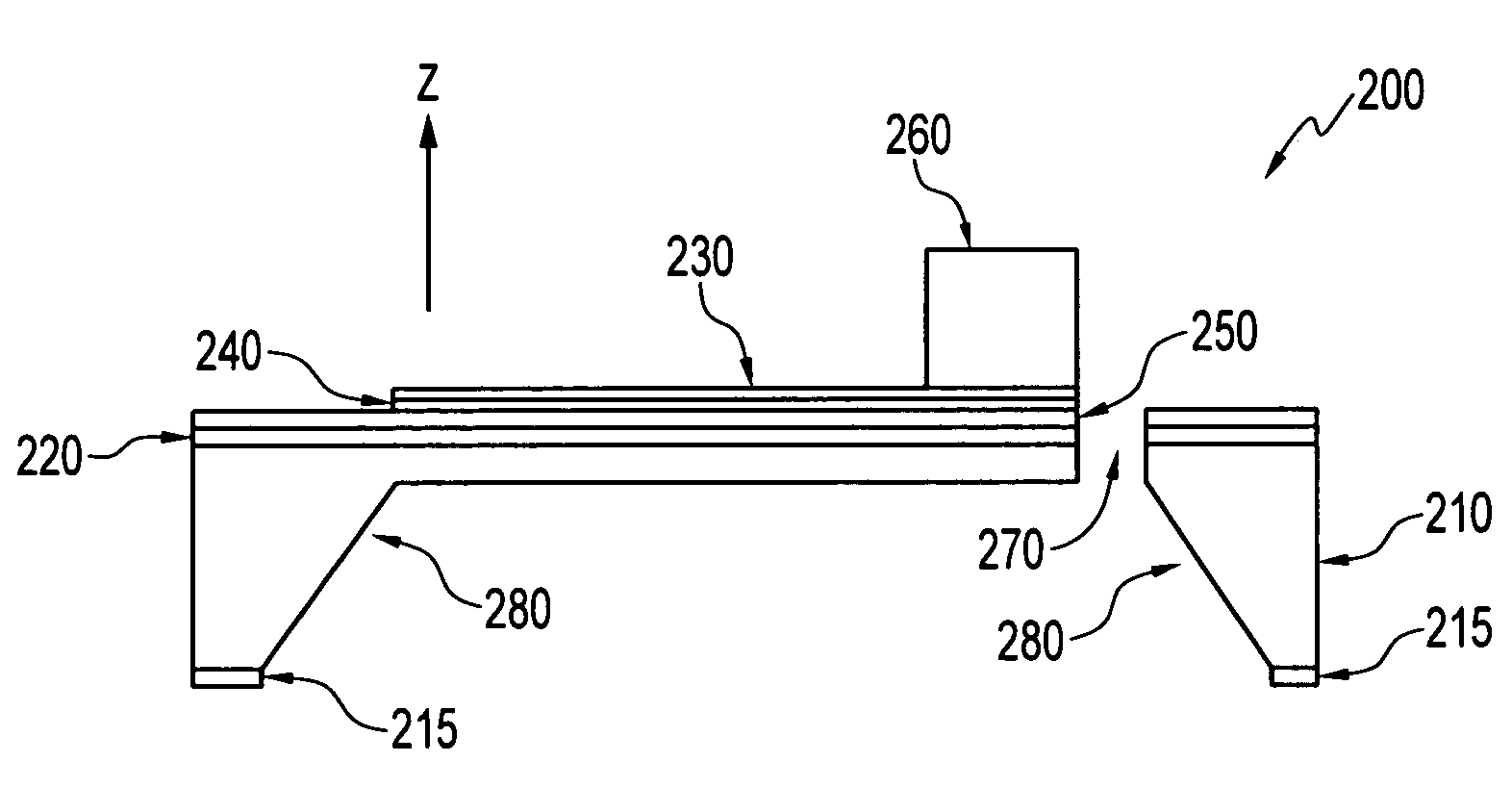
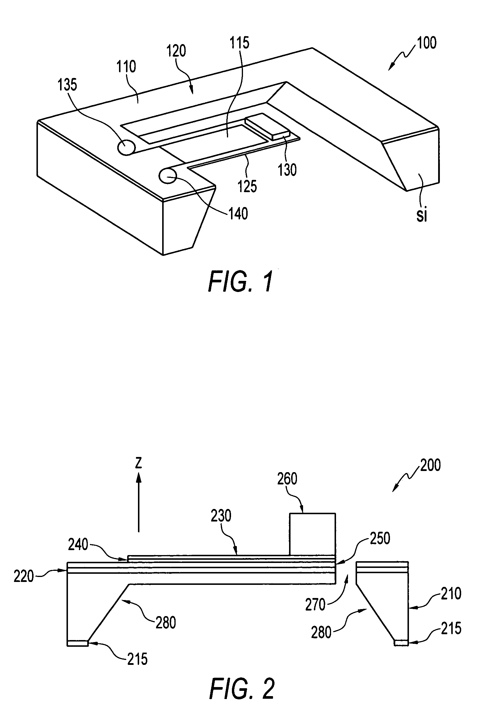
[0015]With reference now to the figures and in particular with reference to FIG. 1, there is depicted an embodiment of a micromachined, piezoelectric power generator 100 including a dielectric frame 110 loosely supporting an integrated piezoelectric panel 125. The piezoelectric panel 125 is composed of dielectric materials and includes an electrode and can be formed as a piezoelectric layer 115 formed over an electrode. An end mass 130 provides enough weight to cause the piezoelectric panel 125 to move (vibrate) within an integrated frame 110. Movement of the panel 120 within the frame 110 causes the generation of electrical power, which can be used to power a microelectronic system such as a sensor. Generated power is taken from connection to lower pad 135 and upper p...


PUM


Abstract

A micro-sized power source. A piezoelectric power generator, capable of harvesting energy from environmental vibration with lower level frequency, including a dielectric frame loosely containing a piezoelectric panel. The piezoelectric panel includes an electrode and a piezoelectric layer formed over an electrode and dielectric layer and an end mass formed on the piezoelectric layer. The end mass provides weight to cause the piezoelectric panel to move (vibrate) within the frame and causes the generation of electrical power.

Description

TECHNICAL FIELD[0001]Embodiments described herein are related to micro power sources. More particularly, embodiments described herein are related to vibration-induced micromachined power harvesting / generating devices. Embodiments are also related to methods of fabricating vibration-induced micromachined power harvesting / generating devices.BACKGROUND OF THE INVENTION[0002]Wireless sensor networks provide promising solutions for broad areas of use ranging from building monitoring to medical implants applications. Wireless sensors provide advantages during wide use of cost savings, installation simplicity, remote control, etc. The problem associated with the concept of a wireless network, however, lies with determining how to supply power to contactless, embedded sensors.[0003]Batteries are automatically thought to be a solution for providing power to remote device, but such power sources are limited by their finite lifetime. In addition, sensor nodes tend to be portable and integrated...

Claims


Application Information

Patent Timeline
Patent Type & Authority Patents(United States)
IPC IPC(8): H01L41/08H01L41/22
CPCH01L41/1136H01L41/22H10N30/306H10N30/01
Inventor XU, ZHENG YI-DANIEL
Owner HONEYWELL INT INC
Why Eureka
Try Eureka