
Method for generating an electro-hydraulic model for control design

a technology of electrohydraulic model and control system, applied in the direction of process and machine control, instruments, analogue processes for specific applications, etc., can solve the problems of slow development time, inability to undertake, and inability to accurately obtain plant dynamics model, so as to reduce the time of product development

Active Publication Date: 2010-03-30
DELPHI TECH IP LTD
View PDF10 Cites 19 Cited by
  • Summary
  • Abstract
  • Description
  • Claims
  • Application Information

AI Technical Summary

Benefits of technology

This approach reduces the product development cycle by allowing control system design to begin before a physical prototype is available, while also providing guidance on how physical design affects overall system dynamic behavior, thereby accelerating development and improving system performance.

Problems solved by technology

However, acquiring an accurate plant dynamics model is a very time consuming and resource intensive undertaking.
In certain instances, such an undertaking is simply not possible given the real-world product development timing requirements.
This leads to slower development times.
While use of the approach in the Rapid Prototyping article can greatly expedite development, its reach is admittedly to only preliminary control algorithm work, and in any event does not provide any direct guidance as to applicability to electro-hydraulic systems.

Method used


Image

  • Method for generating an electro-hydraulic model for control design
  • Method for generating an electro-hydraulic model for control design
  • Method for generating an electro-hydraulic model for control design

Examples


Embodiment Construction

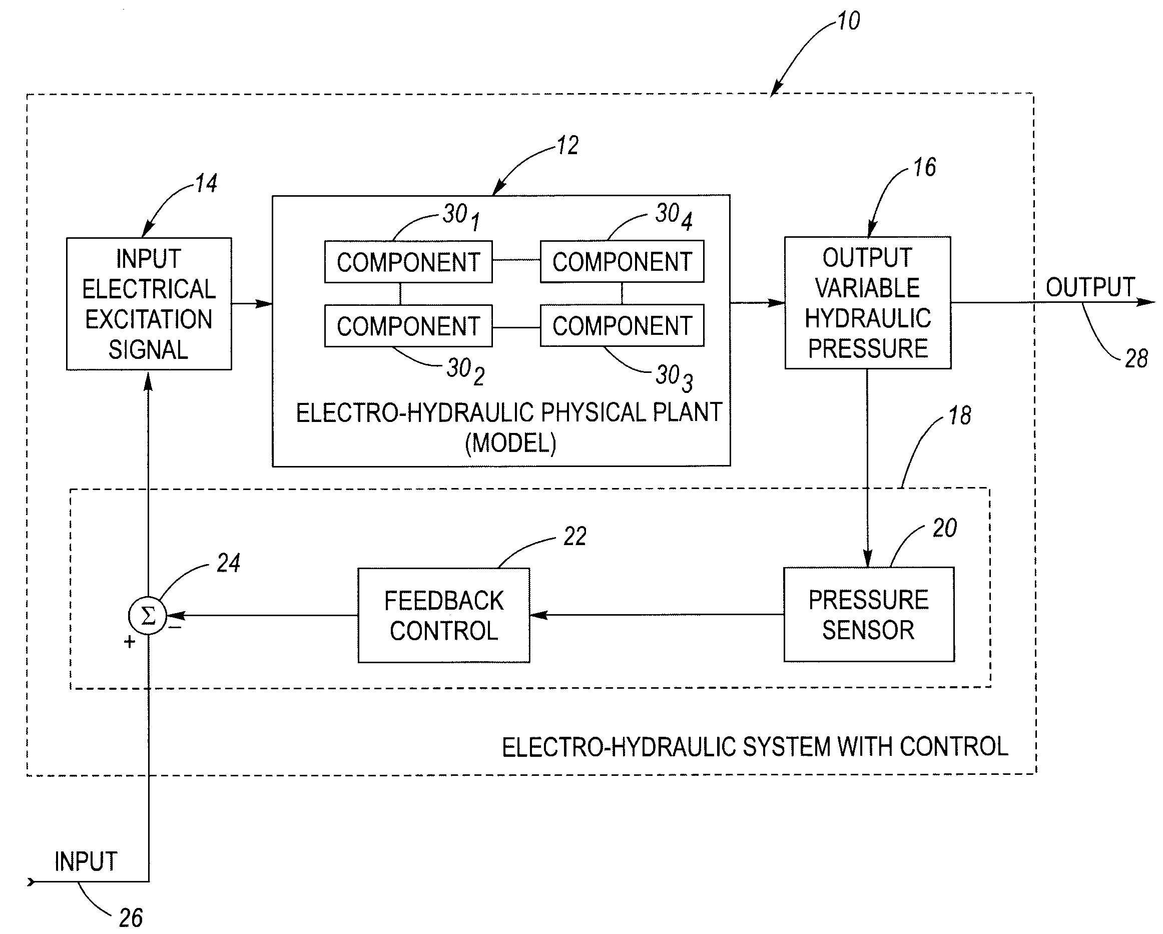
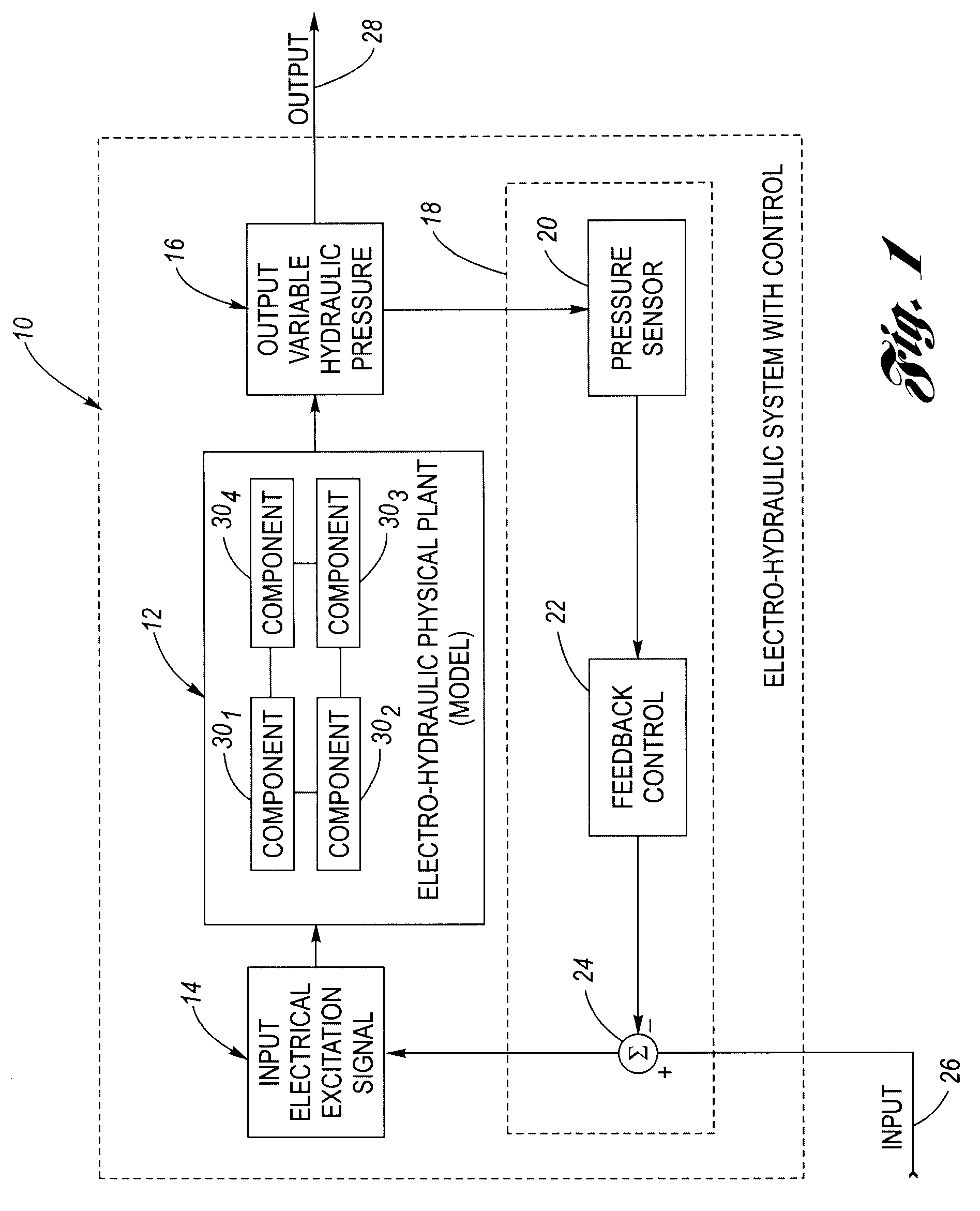
[0018]Referring now to the drawings wherein like reference numerals are used to identify identical components in the various views, FIG. 1 is a simplified block diagram of an electrically-controlled fluid pressure control system 10, which includes an electro-hydraulic (EH) physical plant 12. As described in the Background, in order to design a control system for an electro-hydraulic physical plant, an accurate model of the plant dynamics is conventionally required. However, developing an accurate model is a very time consuming and resource intensive process, and sometimes product development timelines do not allow for such accurate model development. Alternatively, product development timelines may be extended while awaiting development of the plant dynamics model. This conventional sequence essentially serializes the overall process, slowing development.

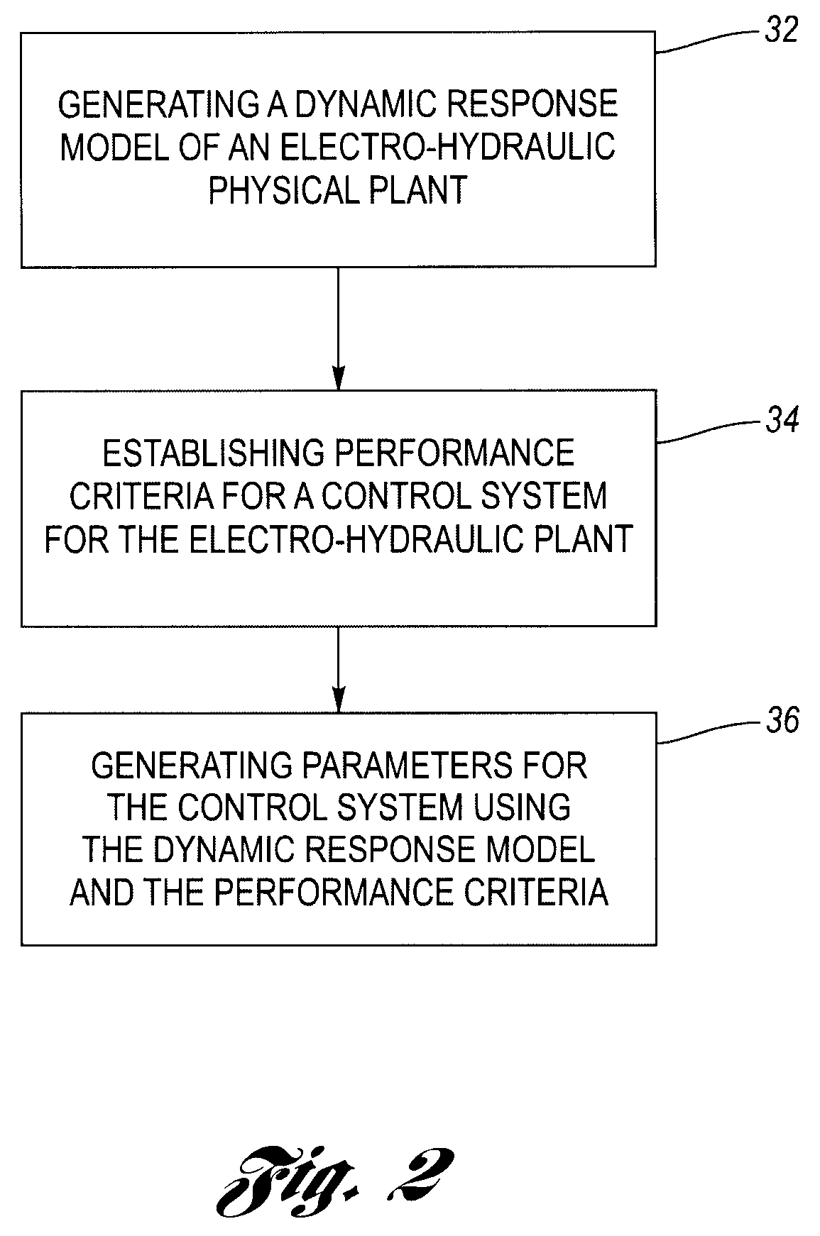
[0019]The present invention provides a systematic methodology to generate a model that accurately represents the dynamic response ...


PUM


Abstract

The dynamic response characteristics of an electro-hydraulic (EH) physical plant is represented by a model. The model includes a series of second order transfer functions, one for each operating point, of the EH physical plant. Command pressure, overshoot, rise time, damping coefficient, natural frequency and gain parameters are determined in developing each transfer function. The model can be used to advance the time in which the design and development of a control system for the EH physical plant can begin.

Description

TECHNICAL FIELD[0001]The present invention relates generally to improvements in control system design, and more particularly, to a method for generating an electro-hydraulic model for control system design.BACKGROUND OF THE INVENTION[0002]Electro-hydraulic systems are used in a variety of industrial and other applications, including the automotive industry. Electro-hydraulic systems may be defined as those involving electrical signals (e.g., an electrical input command signal) and components (e.g., solenoids) that also further involve controlled hydraulic fluid paths and / or pressures. One example may be a two-stage main pressure regulating assembly that may be used in an automatic speed change transmission, where the first stage is a pressure control solenoid (PCS) providing a pilot pressure in response to an input command (i.e., electrical signal) and where the second stage includes a spool valve configured to regulate a main fluid pressure in accordance with the pilot pressure. Th...

Claims


Application Information

Patent Timeline
Patent Type & Authority Patents(United States)
IPC IPC(8): G06F19/00G06G7/50
CPCG05B17/02Y02T10/82
Inventor ZHENG, QUAN
Owner DELPHI TECH IP LTD
Learn More