Lifting control apparatus for window covering

a technology for controlling apparatus and window covering, which is applied in the direction of mechanical apparatus, door/window protective devices, wing accessories, etc., can solve the problems of difficult or smooth lifting of the lift cord, and reducing the life of the window covering. , to achieve the effect of shortening the life span

Active Publication Date: 2010-04-06
CHENG LI MING
View PDF21 Cites 15 Cited by
  • Summary
  • Abstract
  • Description
  • Claims
  • Application Information

AI Technical Summary

Benefits of technology

[0007]The primary object of the present invention is to provide a window covering lifting control apparatus to solve the problems of poor locating effect and shorter life span occurred to the conventional window covering lifting control apparatus mentioned above.
[0009]By means of the construction set forth above, the following main functions can be achieved: The window lifting control apparatus can be installed in a lower elongated member of a window covering to control retraction upward or extension downward of the window covering. The two gears of the locating set can engage with and latch the lift cord assembly of the window covering to provide an improved locating effect. Such a structure also can better bear the weight of the window covering. The spring assembly and the springs can jointly bear the force, thereby the life span of the window lifting control apparatus increases.

Problems solved by technology

1. Poor locating: The lifting control apparatus 15 clamps the lift cord assembly 14 through merely the button 151 and retaining member 152. As the general lift cord assembly 14 has to bear the weight of the blind 13, when the weight of the blind 13 is great, the locating effect of the lifting control apparatus 15 on the lift cord assembly 14 is limited. As a result, retracting or extending the window covering 1 is not always easy or smooth.
2. Shorter life span: The function of the lifting control apparatus 15 is mainly achieved through the elastic expansion and compression of the spring 153 to clamp the lift cord assembly 14 between the button 151 and the retaining member 152. As the lift cord assembly 14 has to bear the weight of the blind 13, the spring 153 is subject to a great force. After used for a period of time, elastic fatigue occurs to the spring, and the clamping and locating effect of the button 151 and retaining member 152 diminish. The life span of the brake means 15 suffers.
And elastic fatigue also occurs after used for a period of time.

Method used


Image

  • Lifting control apparatus for window covering
  • Lifting control apparatus for window covering
  • Lifting control apparatus for window covering

Examples


Embodiment Construction

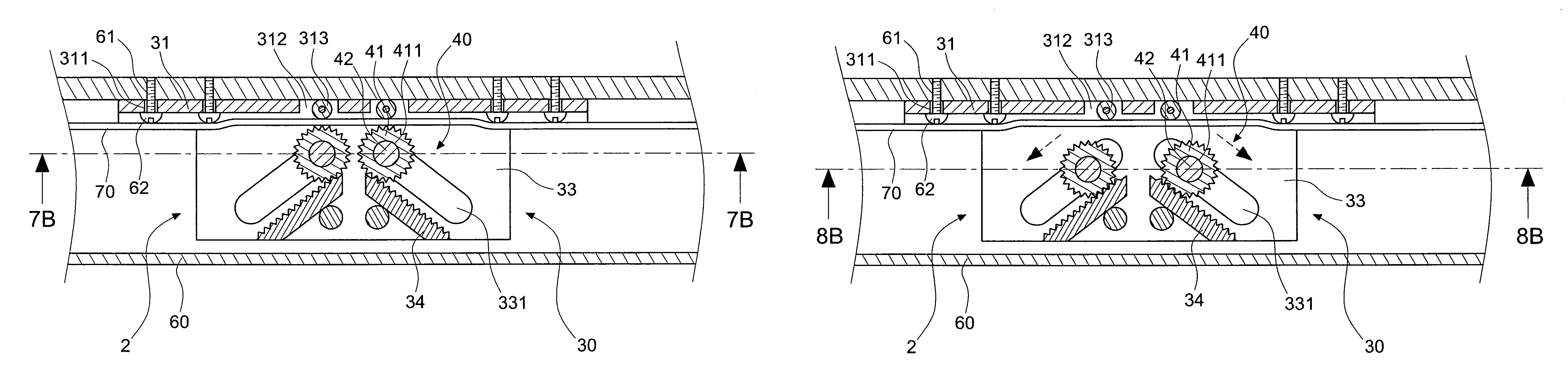
[0029]Please refer to FIGS. 5A and 6, the window covering lifting control apparatus 2 according to the invention includes a holding unit 30, a locating set 40 and a pushbutton 50.

[0030]The holding unit 30 has a bracket 31 which has an aperture 311 and two openings 312 in a middle portion to hold rollers 313. The bracket 31 has a bottom side forming a first spacer 32 and a second spacer 33 in a spaced manner. The first spacer 32 has two first slots 321 corresponding to the two rollers 313. The two first slots 321 are inclined downwards towards two sides of the first spacer 32. The first spacer 32 has one side opposing the second spacer 33 that has a strut 322 formed thereon. The strut 322 is coupled with a spring 323 on an outer side. As depicted in an embodiment shown in the drawings, the number of the strut 322 may be two spaced from each other in an up and down manner. The second spacer 33 also has two second slots 331 corresponding to the two rollers 313 that are inclined downwar...


PUM


Abstract

A window covering lifting control apparatus includes a holding unit, a locating set and a pushbutton. The holding unit has a first spacer and a second spacer formed thereon that are spaced from each other. The spacers have two slots inclining downwards. The first spacer has a strut on one side to be coupled with a spring on an outer side. The locating set includes two gears, two locating rods, two locating heads and a spring assembly to hold the two gears between the spacers. The pushbutton is movably coupled on the strut of the holding unit to control movement of the two gears in the slots. The window lifting control apparatus can be installed in a lower elongated member to control retraction upward or extension downward of the window covering. The two gears of the locating set can engage with and latch a lift cord assembly to provide improved locating effect.

Description

FIELD OF THE INVENTION[0001]The present invention relates to a window covering lifting control apparatus and particularly to a lifting control apparatus installed on a lower elongated member of a window covering to control retraction or extension of the window covering.BACKGROUND OF THE INVENTION[0002]Referring to FIGS. 1 and 2, U.S. Pat. No. 6,675,861 discloses a brake for a cordless blind in which a window covering 1 includes a head rail 11, a bottom rail 12 and a blind 13 located between the head rail 11 and the bottom rail 12. The window covering 1 also has a lift cord assembly 14 linking to the blind 13. The bottom rail 12 has a lifting control apparatus 15 which has a button 151 extended from the front side of the bottom rail 12 and a retaining member 152 held in the bottom rail 12 in an extensible manner through a spring 153. The button 151 and the retaining member 152 can clamp the lift cord assembly 14 to harness the movement of the lift cord assembly 14 and the blind 13. R...

Claims


Application Information

Patent Timeline
Patent Type & Authority Patents(United States)
IPC IPC(8): E06B9/324E06B9/30F16G11/02
CPCE06B9/322Y10T24/3976
Inventor CHENG, LI-MING
Owner CHENG LI MING
Why Eureka
Try Eureka