Ultra-wideband shorted dipole antenna

a dipole antenna and ultra-wideband technology, applied in the direction of antenna feed intermediates, resonance antennas, radiating element structural forms, etc., can solve the problems of increased cost of manufacturing antennas, increased cost of antennas, and increased complexity of overall antenna structure, etc., to achieve simple structure, low cost, and easy manufacturing

Active Publication Date: 2010-04-06
NAT SUN YAT SEN UNIV +1
View PDF14 Cites 6 Cited by
  • Summary
  • Abstract
  • Description
  • Claims
  • Application Information

AI Technical Summary

Benefits of technology

[0008]The invention is directed to an ultra-wideband shorted dipole antenna capable of generating an ultra-wideband impedance bandwidth ranging from 820 to 7350 MHz (the frequency ratio is about 9:1) in the wireless communication band. In addition, the dipole antenna has the simple structure, may be combined with a plane object, may be easily manufactured and has the low cost, and may be properly mounted indoors, outdoors or on a traffic vehicle to serve as a signal receiving antenna for the wireless communication band.
[0011]According to the experimental result of the invention, the antenna of the invention can generate an ultra-wideband impedance bandwidth with a frequency ratio of about 9:1 in the wireless communication band, and the antenna radiation pattern and the antenna gain can satisfy the actual application of receiving the wireless communication band signal. In this invention, two simple open-loop radiating metal plates constitute two arms of the dipole antenna so that the resonance current path of the antenna can be lengthened and the size of the antenna can be reduced. In addition, one short-circuiting thin metal plate or a plurality of simple short-circuiting thin metal plates is electrically connected to the dipole antenna constituted by the two simple open-loop radiating metal plates in order to adjust the impedance matching of the antenna. Thus, the antenna of the invention can achieve the ultra-wideband impedance bandwidth in the wireless communication band. In practice, the coaxial cable line can be placed in a region without a metal plate and surrounded by the two open-loop radiating metal plates and an opening thereof so as to prevent the coaxial cable line from influencing the radiation property of the antenna. Because the antenna of the invention has the simple structure, can be combined with a plane object, can be easily manufactured and has the low cost, the antenna can be properly mounted indoors, outdoors or on the traffic tool to serve as the signal receiving antenna for the wireless communication band.

Problems solved by technology

The multiple antenna systems require multiple coaxial signal cable lines, and the problems of the increased cost of manufacturing the antennas, the wasted space for accommodating the antennas and the electromagnetic interference have to be solved.
However, the overall structure of the antenna becomes more complicated and the size thereof is significantly increased.
However, if the notch antenna has to be configured to operate in a lower band, the size of the antenna is also too large, the antenna cannot be properly attached to the vehicle window or hidden in a vehicle bumper, and the good impedance matching cannot be achieved in the resonance band.
However, the helical antenna has the complicated structure, the signal feeding portion needs an additional Balun to achieve the better impedance matching.
The manufacturing cost of the antenna is increased due to the required Balun and the additionally loaded multi-layer medium.

Method used


Image

  • Ultra-wideband shorted dipole antenna
  • Ultra-wideband shorted dipole antenna
  • Ultra-wideband shorted dipole antenna

Examples


first embodiment

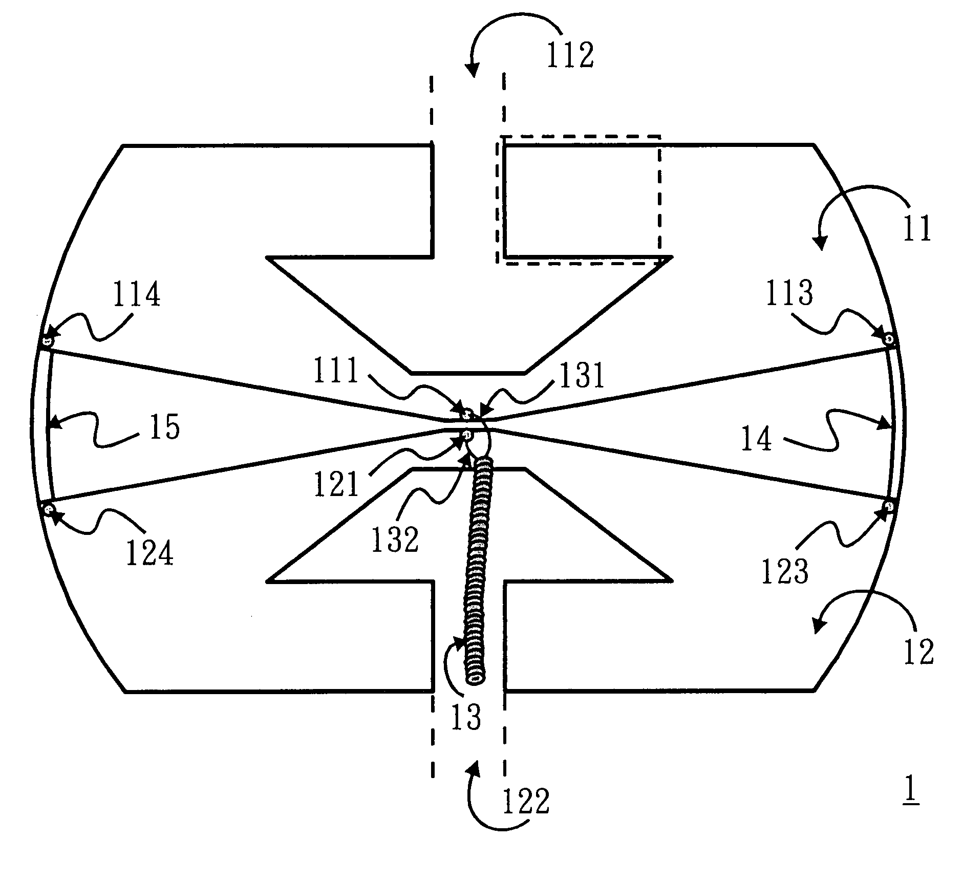
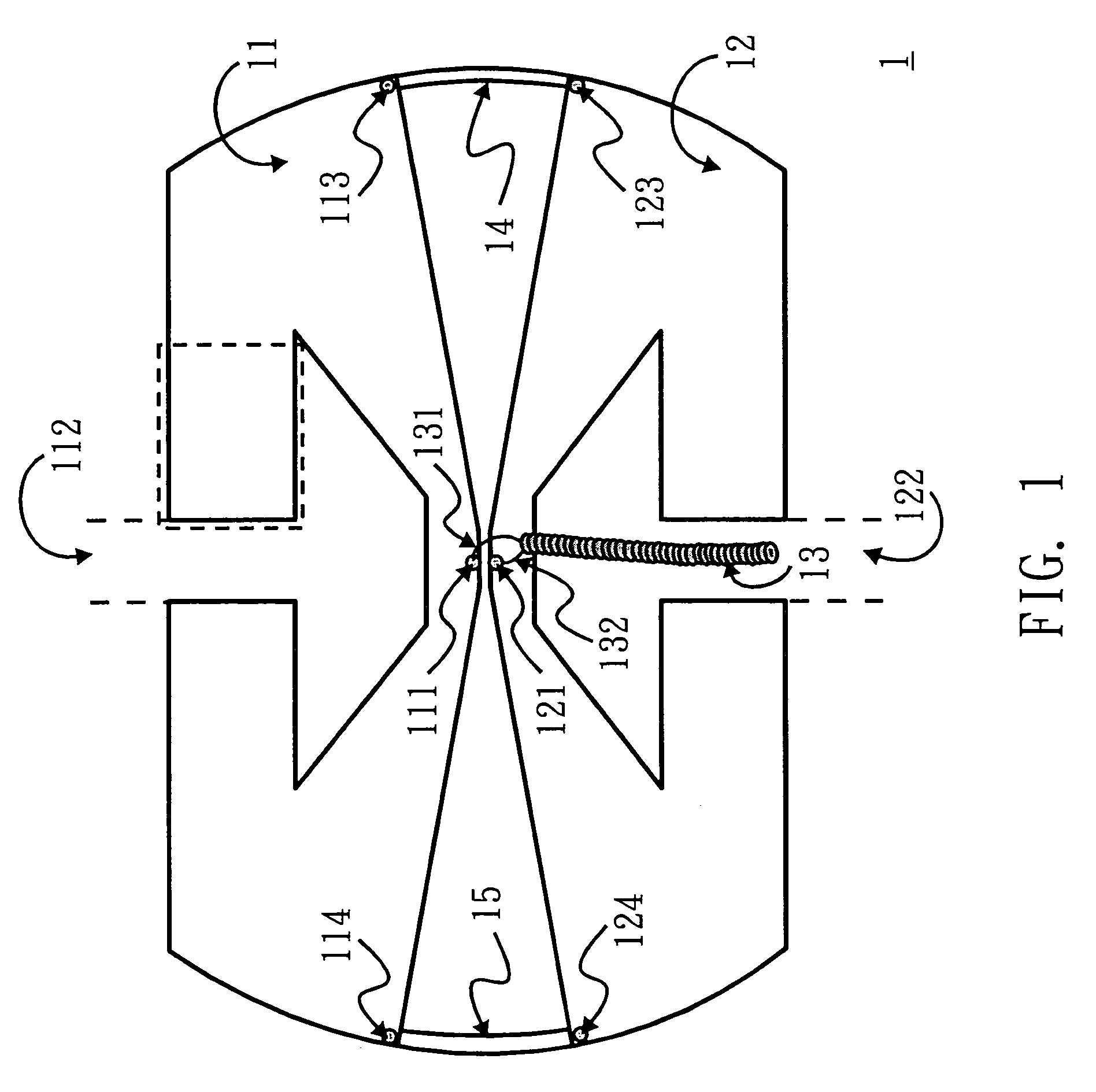
[0020]FIG. 1 is a structural diagram showing an ultra-wideband shorted dipole antenna 1 according to a first embodiment of the invention. Referring to FIG. 1, the ultra-wideband shorted dipole antenna 1 includes a coaxial cable line 13 and first and second open-loop radiating metal plates 11 and 12 having substantially the same shape. The coaxial cable line 13 has a central conducting wire 131 and an outer grounder sheath 132. The first and second open-loop radiating metal plates 11 and 12 respectively have signal feeding points 111 and 121 and openings 112 and 122 and are substantially disposed on two sides of the ultra-wideband shorted dipole antenna 1 symmetrically to form two arms of the ultra-wideband shorted dipole antenna 1.

[0021]As shown in FIG. 1, the first and second open-loop radiating metal plates 11 and 12 are disposed symmetrically so that the two openings 112 and 122 have opposite outward directions and the signal feeding points 111 and 121 are disposed adjacent to ea...

second embodiment

[0029]FIG. 7 is a structural diagram showing an ultra-wideband shorted dipole antenna according to a second embodiment of the invention. As shown in FIG. 7, what is different from the first embodiment is that first and second open-loop radiating metal plates 71 and 72 of the ultra-wideband shorted dipole antenna 2 in the second embodiment are formed on a medium substrate 70 by way of etching or printing. In addition, the external shapes of the open-loop radiating metal plates 71 and 72 and the shapes of the inner edges of openings 712 and 722 are adjusted according to the consideration of the manufacturing and the actual application, wherein the overall antenna has a rectangular shape different from the arced shapes on two sides of the antenna of the first embodiment. The resonance current path of the antenna can be lengthened and the size of the antenna can be reduced according to the configuration of the openings 712 and 722 and short-circuiting thin metal plates 74 and 75. In add...

third embodiment

[0030]FIG. 8 is a structural diagram showing an ultra-wideband shorted dipole antenna according to a third embodiment of the invention. The ultra-wideband shorted dipole antenna 3 includes a coaxial cable line 83 and first and second open-loop radiating metal plates 81 and 82 having substantially the same shape. The coaxial cable line 83 has a central conducting wire 831 and an outer grounder sheath 832. The first and second open-loop radiating metal plates 81 and 82 respectively have signal feeding points 811 and 821 and openings 812 and 822 and are substantially disposed on two sides of the ultra-wideband shorted dipole antenna 3 symmetrically to form two arms of the ultra-wideband shorted dipole antenna 3. Compared with FIG. 1, the ultra-wideband shorted dipole antenna 3 only has one single short-circuiting thin metal plate 84, which is electrically connected to a short-circuited point 813 of the first open-loop radiating metal plate 81 and a short-circuited point 823 of the seco...


PUM


Abstract

An ultra-wideband shorted dipole antenna includes a coaxial cable line and first and second open-loop radiating metal plates with substantially the same shape. The coaxial cable line has a central conducting wire and an outer grounder sheath. The first and second open-loop radiating metal plates are symmetrically disposed on two sides of the antenna to form two arms of the antenna and are electrically connected to each other. Each of the first and second open-loop radiating metal plates has a signal feeding point electrically connected to the central conducting wire or the outer grounder sheath of the coaxial cable line.

Description

[0001]This application claims the benefit of Taiwan application Serial No. 96101962, filed Jan. 18, 2007, the subject matter of which is incorporated herein by reference.BACKGROUND OF THE INVENTION[0002]1. Field of the Invention[0003]The invention relates in general to a dipole antenna, and more particularly to an ultra-wideband shorted dipole antenna that may be applied to a wireless communication band.[0004]2. Description of the Related Art[0005]Currently, the wireless communication frequency spectrum has been full with many application bands of the commercial wireless communication systems, such as the advanced mobile phone system (AMPS) ranging from 824 to 894 MHz, the global system for mobile communication (GSM) ranging from 880 to 960 MHz, the digital communication system (DCS) ranging from 1710 to 1880 MHz, the personal communication services (PCS) ranging from 1850 to 1990 MHz), the universal mobile telecommunication system (UMTS) ranging from 1920 to 2170 MHz and the worldw...

Claims


Application Information

Patent Timeline
Patent Type & Authority Patents(United States)
IPC IPC(8): H01Q9/28H01Q9/04H01Q9/16
CPCH01Q9/285H01Q5/371H01Q5/25H01Q13/10
Inventor WONG, KIN-LULI, WEI-YUSU, SAOU-WEN
Owner NAT SUN YAT SEN UNIV
Why Eureka
Try Eureka