Head suspension having wiring disposed in contact with slightly conductive flexible resin

a flexible resin and wire suspension technology, applied in the field of head suspension, can solve the problems of static electricity accumulated in the wires moving to the magnetic head to deteriorate or destroy the read element of the magnetic head, require an electrostatic discharge damage preventive measure, and require no cost increase. , to prevent the effect of electrostatic discharge through the read element and preventing the effect of electrostatic destruction of the read elemen

Active Publication Date: 2010-04-06
NHK SPRING CO LTD
View PDF32 Cites 45 Cited by
  • Summary
  • Abstract
  • Description
  • Claims
  • Application Information

AI Technical Summary

Benefits of technology

[0008]An object of the present invention is to provide a head suspension capable of preventing electrostatic discharge damage of a read element without a static electricity remover that may cause a cost increase.
[0010]According to this aspect, the insulating base or cover layer at least for read wires is made of slightly conductive flexible resin. Static electricity accumulated in the read wires can be discharged through the insulating base or cover layer to a flexure of the head suspension, or can be discharged from the insulating cover layer to the atmosphere. This results in preventing electrostatic discharge through a read element of a head, to thereby preventing an electrostatic destruction of the read element. Forming the insulating base or cover layer from slightly conductive flexible resin involves no additional process and no cost increase and is easy to carry out.

Problems solved by technology

If the magnetic head of the head suspension touches a tool or a jig, the static electricity accumulated in the wires will move to the magnetic head to deteriorate or destroy a read element of the magnetic head.
These elements are vulnerable to static electricity and require an electrostatic discharge (ESD) damage preventive measure.

Method used


Image

  • Head suspension having wiring disposed in contact with slightly conductive flexible resin
  • Head suspension having wiring disposed in contact with slightly conductive flexible resin
  • Head suspension having wiring disposed in contact with slightly conductive flexible resin

Examples


first embodiment

[0030][General Structure of Head Suspension]

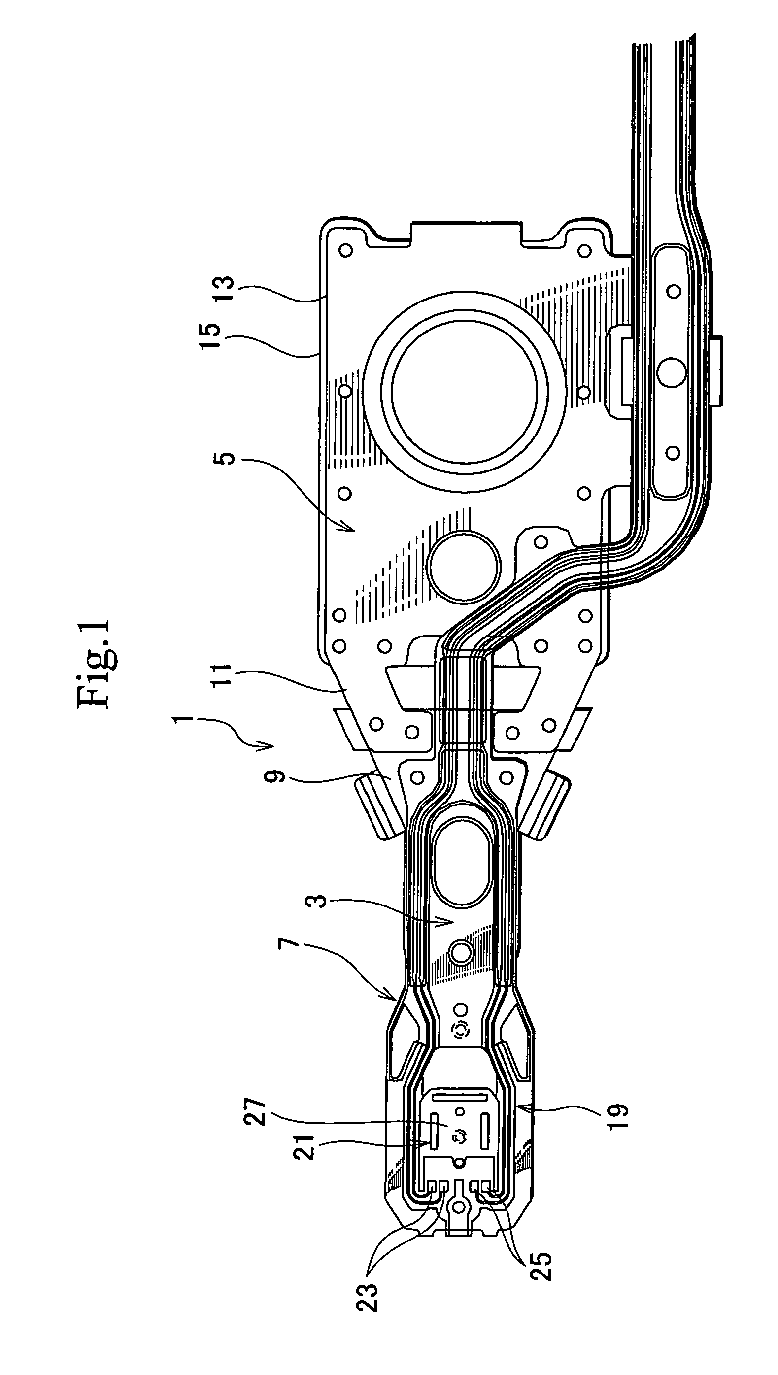
[0031]FIG. 1 is a plan view showing a head suspension according to a first embodiment of the present invention.

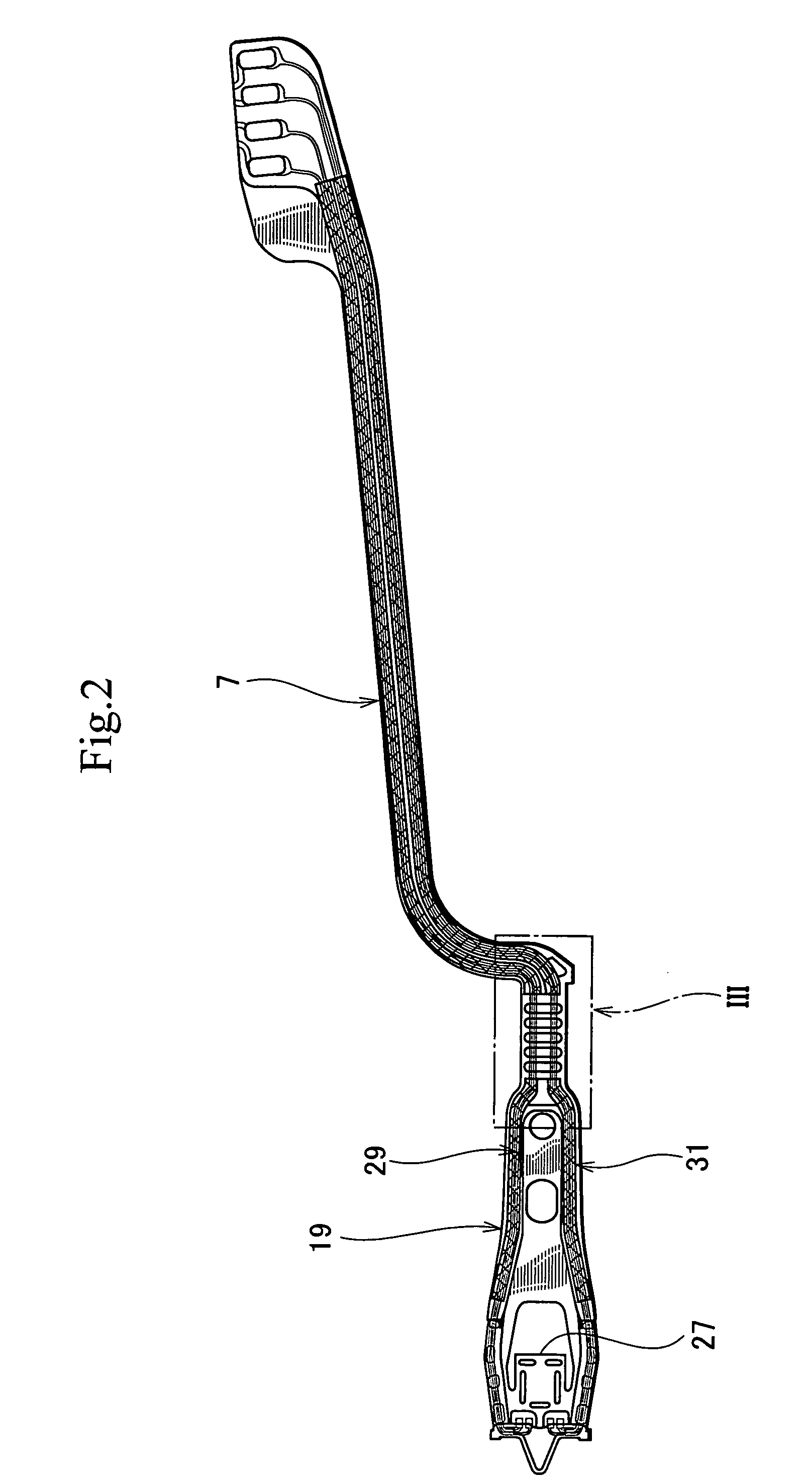
[0032]In FIG. 1, the head suspension 1 has a load beam 3, a base 5, and a flexure 7.

[0033]The load beam 3 includes a rigid part 9 and a resilient part 11, to apply load to a head 21. The rigid part 9 is made of, for example, stainless steel and is relatively thick. The thickness of the rigid part 9 is, for example, about 100 μm.

[0034]The resilient part 11 is a separate part from the rigid part 9 and is made of, for example, a resilient thin stainless-steel rolled plate. The spring constant of the resilient part 11 is precise and is lower than that of the rigid part 9. The thickness of the resilient part 11 is, for example, about 40 μm. A front end of the resilient part 11 is fixed to a rear end of the rigid part 9 by, for example, laser welding. A rear end of the resilient part 11 is integral with a reinforcing plate 13.

[0035]The ...

second embodiment

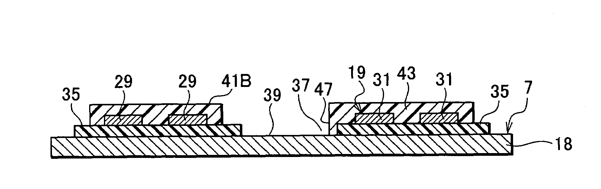
[0059]FIG. 6 is a sectional view showing a head suspension according to a second embodiment of the present invention, taken at a location corresponding to the location along the line IV-IV of FIG. 3. The structure of the second embodiment is basically the same as that of the first embodiment of FIG. 4, and therefore, the same or corresponding parts are represented with the same reference numerals or the same reference numerals plus “A” in FIG. 6.

[0060]The second embodiment omits the insulating cover layers 41 and 43 of FIG. 4 and employs an insulating base layer 35A made of slightly conductive flexible resin having a surface resistivity in the range of 104 to 1011 Ω / sq instead of the insulating base layer 35 of FIG. 4.

[0061]To manufacture the head suspension according to the second embodiment, the process of FIG. 5A employs slightly conductive flexible resin to form a polyimide insulating film 53. The film 53 has a thickness in the range of 5 to 20 μm and serves as the insulating ba...

third embodiment

[0064]FIG. 7 is a sectional view showing a head suspension according to a third embodiment of the present invention, taken at a location corresponding to the location along the line IV-IV of FIG. 3. The structure of the third embodiment is basically the same as that of the first embodiment of FIG. 4, and therefore, the same parts are represented with the same reference numerals in FIG. 7.

[0065]Instead of the separate insulating base layer 35 and insulating cover layers 41 and 43 of the first embodiment of FIG. 4, the third embodiment of FIG. 7 employs insulating base / cover layers 65 and 67. Each of the layers 65 and 67 is an integration of insulating base and cover layers and is made of slightly conductive flexible resin having a surface resistivity in the range of 104 to 1011 Ω / sq.

[0066]To manufacture the head suspension according to the third embodiment, the process of FIG. 5A employs slightly conductive flexible resin to form a polyimide insulating film 53. The film 53 has a thic...


PUM

PropertyMeasurementUnit
thicknessaaaaaaaaaa
thicknessaaaaaaaaaa
thicknessaaaaaaaaaa

Abstract

A head suspension prevents a read element from electrostatic discharge damage without employing a static electricity remover or without increasing the number of manufacturing processes. The head suspension has a load beam to apply load to a head that writes and reads data to and from a hard disk, a flexure made of a conductive thin substrate attached to the load beam and supporting the head, an insulating base layer made of flexible resin and formed on the substrate of the flexure, write wires and read wires connected to the head and formed on the insulating base layer, and an insulating cover layer covering the write and read wires on the insulating base layer. The insulating cover layer is made of slightly conductive flexible resin.

Description

BACKGROUND OF THE INVENTION[0001]1. Field of the Invention[0002]The present invention relates to a head suspension for a hard disk drive installed in an information processing apparatus such as a computer.[0003]2. Description of Related Art[0004]A hard disk drive (HDD) employs a head suspension for suspending a magnetic head to write and read data to and from a magnetic disk. To transfer write and read signals to and from the magnetic head, wires are connected to the magnetic head. The wires are arranged on an insulating base layer that is made of flexible resin and is formed on a flexure. The flexure is a part of the head suspension and is made of a resilient stainless-steel thin plate. The wires are covered with an insulating cover layer made of flexible resin.[0005]When the flexure is assembled into the head suspension, the surface of the insulating cover layer may be rubbed with another part such as a clamp or a tool, to accumulate static electricity. This static electricity is ...

Claims


Application Information

Patent Timeline
Patent Type & Authority Patents(United States)
IPC IPC(8): G11B21/16G11B5/48
CPCG11B5/10G11B5/4853H05K1/0259H05K1/167H05K1/056G11B21/16
Inventor ARAI, HAJIMESOMEYA, IKUOKAWATAKE, RYUICHIHIGASHI, TSUKASA
Owner NHK SPRING CO LTD
Why Eureka
Try Eureka