Transmitter and method of transmission

a technology of transmitters and transmission paths, applied in the field of transmitters and transmission methods, can solve the problems of reduced transmission efficiency of packets, increased network load on the route onto which data packets were transmitted, and increased traffic and loss of transmitted packets, so as to improve the quality of transmission paths, reduce data congestion, and enhance packet transmission efficiency

Inactive Publication Date: 2010-04-06
FUJITSU LTD
View PDF17 Cites 0 Cited by
  • Summary
  • Abstract
  • Description
  • Claims
  • Application Information

AI Technical Summary

Benefits of technology

[0039]Thus, according to the present invention, the table of the relay section stores information about the relay of a received packet to a transmission path port connected with a relay transmission path by which the received packet reaches its destination, and correlates the relay information with both the port identifier of each transmission path port that receives a packet and the address of a source transmitter that transmitted the received packet. The router routes a received packet by referring to the above-described table, based on the port identifier of a transmission path port that received a packet and on the source address contained in the received packet. Therefore, packet transmission efficiency can be enhanced, data congestion can be minimized, and the quality of transmission paths can be improved.
[0040]In addition, the table stores information that a received packet is not relayed if it circulates through a network, and information that a received packet is relayed if it does not circulate through a network. In this way, whether a data packet transmitted from the transmitter is transmitted to an individual address or multiple addresses, the circulation of the data packet can be prevented in an interval through which a data packet can circulate, such as a ring network, a mesh network, etc. Therefore, data congestion can be minimized, a reduction in traffic can be realized, and the quality of transmission paths can be enhanced.
[0041]In addition, in the case where a path to a destination transmitter is divided into a plurality of paths and has a redundant structure, transmission path ports to relay a received packet are assigned by the table so that many of them are not connected only to one of the paths. Thus, by efficiently utilizing the redundant structure, an increase in the networking load on the side where a data packet is transmitted can be prevented. In addition, an increase in traffic and the loss of transmitted packets can be minimized and packet transmission efficiency can be exponentially enhanced.

Problems solved by technology

However, the network 4 shown in FIG. 13 has the following problems when transmitting data packets by the aforementioned first transmission method, using transmitters such as that shown in FIG. 12.
In this case, the problem of an increase in traffic and the loss of transmitted packets will easily arise and result in a reduction in the quality of transmission paths.
In addition, the network 4A shown in FIG. 16 has the following problems when transmitting data packets by the aforementioned second transmission method.
Because of this, the network load on the route onto which data packets were transmitted is increased, and consequently, an increase in traffic and the loss of transmitted packets tend to take place.
Therefore, even if this technique is used in the transmitters of the networks 4 and 4A shown in FIGS. 13 and 16, an increase in traffic and the loss of transmitted packets can not be prevented.
Therefore, even if this technique is employed in the transmitters of the networks 4 and 4A shown in FIGS. 13 and 16, an increase in traffic and the loss of transmitted packets can not be prevented.

Method used


Image

  • Transmitter and method of transmission
  • Transmitter and method of transmission
  • Transmitter and method of transmission

Examples


Embodiment Construction

[0060]Embodiments of the present invention will hereinafter be described in detail with reference to the drawings.

[0061][A] Description of a Transmitter According to a Preferred Embodiment of the Present Invention

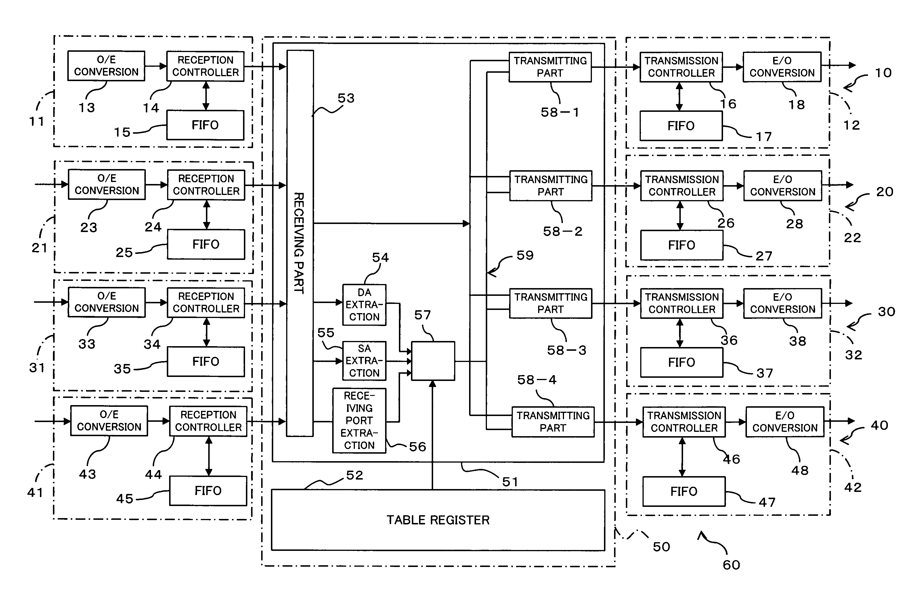
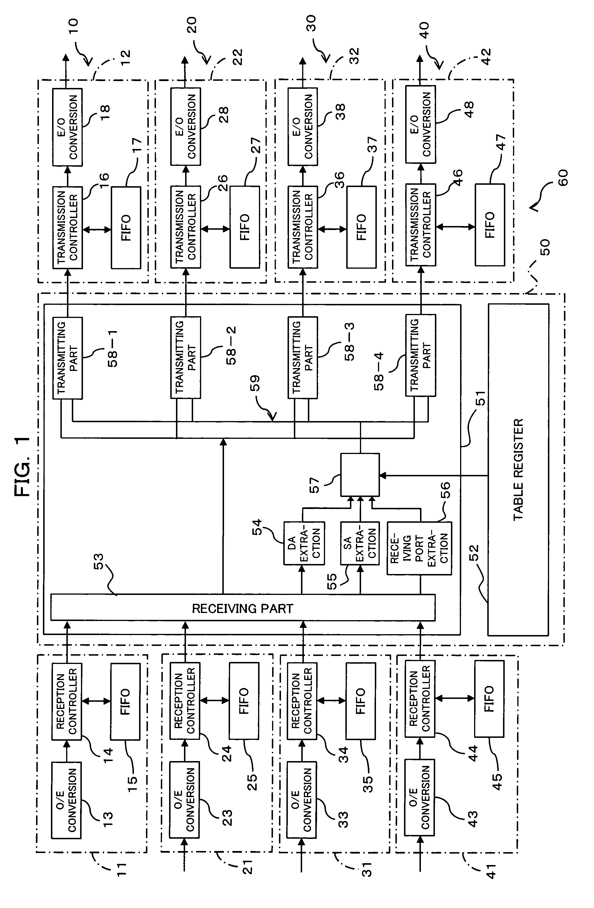
[0062]FIG. 1 shows a transmitter 60 constructed in accordance with a preferred embodiment of the present invention. The transmitter 60 includes receiving port sections 11, 21, 31, 41, transmitting port sections 12, 22, 32, 42, and a relay section 50. A plurality of transmitters with a specific address such as the transmitter 60 are connected through a transmission path such as optical fiber, and are used in a network where a packet with address information about a source transmitter is transmitted.

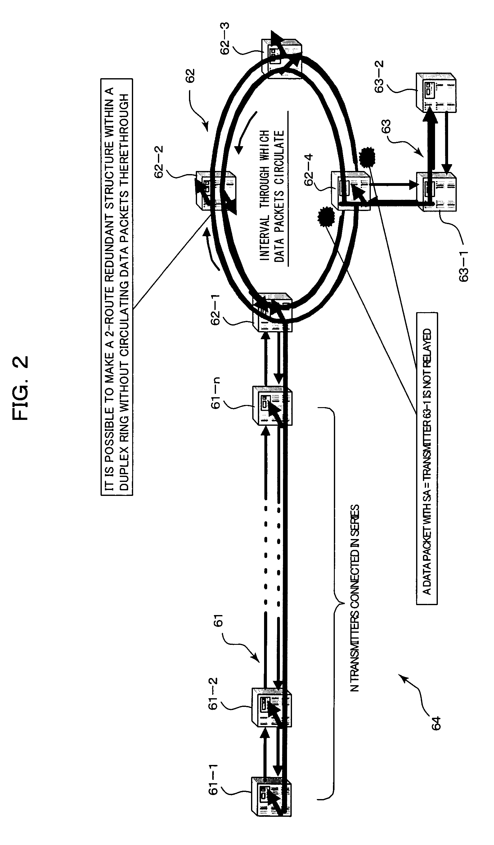
[0063]That is, by employing transmitters such as the transmitter 60 shown in FIG. 1, networks 64 and 64A can be constructed as shown in FIGS. 2 and 7. In addition, in a network, in which a plurality of transmitters with a structure like that shown in FIG. 1 are connected through o...


PUM


Abstract

A transmitter equipped with a plurality of transmission path ports and a relay section. The relay section has a routing table and a router. In the routing table, information about the relay of the received packet to one of the transmission path ports connected to a relay transmission path is stored, correlated with both a port identifier of each the transmission path port and the source address of the transmitter that transmitted the packet. The router extracts the port identifier of the transmission path port that received the packet and the source address contained in the received packet, and routes the received packet to the transmission path port connected to the relay transmission path by referring to the routing table for the extracted port identifier and the extracted source address.

Description

BACKGROUND OF THE INVENTION[0001]1) Field of the Invention[0002]The present invention relates to transmitters and a method of transmission that are used in a network where data packets are transferred between a source transmitter and a destination transmitter via a relay transmitter, and relates more particularly to transmitters and a transmission method that are suitably employed in a vast and complex network where data transmission between certain points is performed via a redundant path structure (consisting of a plurality of paths) to ensure reliability.[0003]2) Description of the Related Art[0004]In networks, in which transmission path ports in transmitters are connected through transmission paths such as optical fiber paths, data communications is performed between transmitters.[0005]In a first method of transmission, it is judged whether a data packet received by one transmission path port in a transmitter is relayed to another transmission path port which relays the received...

Claims


Application Information

Patent Timeline
Patent Type & Authority Patents(United States)
IPC IPC(8): H04L12/28H04L12/427H04L45/18
CPCH04L45/00H04L12/427
Inventor GOTOH, TOMONORITANAKA, KATSUMINAGAO, HIROAKI
Owner FUJITSU LTD
Why Eureka
Try Eureka