
Regulator device for compensating for dispersions of injectors

a technology of injector dispersions and regulator devices, which is applied in the direction of electrical control, process and machine control, instruments, etc., can solve the problems of inflammation dropout, fluctuation between combustion cycles, and rise in temperature, so as to achieve precise and convenient operation of internal combustion engines

Inactive Publication Date: 2010-04-06
VITESCO TECH GERMANY GMBH
View PDF11 Cites 4 Cited by
  • Summary
  • Abstract
  • Description
  • Claims
  • Application Information

AI Technical Summary

Benefits of technology

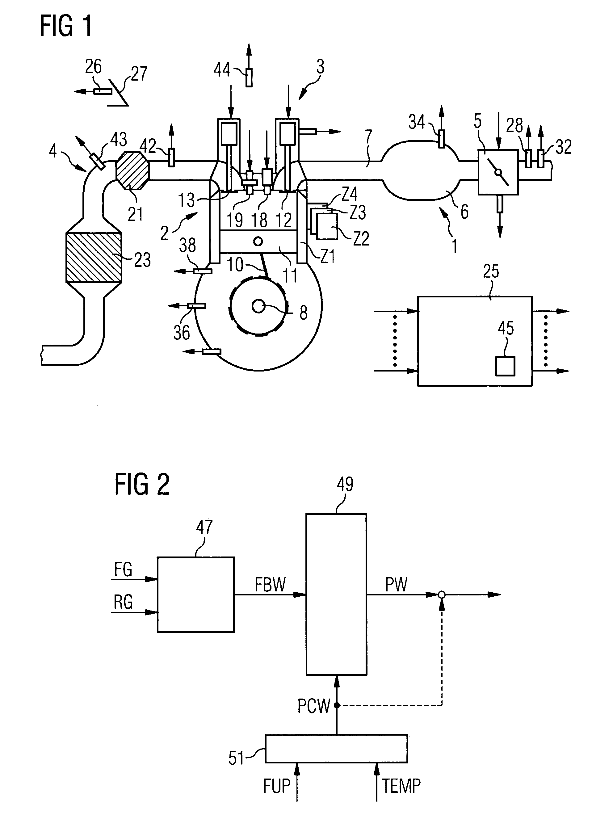
The invention is a regulator device for compensating for dispersions of injectors in internal combustion engines. The device uses a piezo actuator to control the injection of fluid into the engine's cylinders. The device includes a manipulated variable splitting unit that determines a total value of the primary manipulated variable by combining a primary control value and a command value. The manipulated variable splitting unit splits the total value into a primary value and a secondary value based on predetermined thresholds. This allows for a precise and convenient operation of the injector, ensuring even injection of fluid and reducing rotational irregularities in the engine. The device also includes a regulator value that is determined by a pilot control value, which is determined based on at least one operating variable of the engine. The secondary manipulated variable is a variable that represents the injection period of the injector. Overall, the device provides a simple and reliable solution for precise operation of the injector and ensures a smooth running of the engine.

Problems solved by technology

As the lean shift increases however the fluctuations between the combustion cycles rise, until finally inflammation dropouts occur.

Method used


Image

  • Regulator device for compensating for dispersions of injectors
  • Regulator device for compensating for dispersions of injectors
  • Regulator device for compensating for dispersions of injectors

Examples


first embodiment

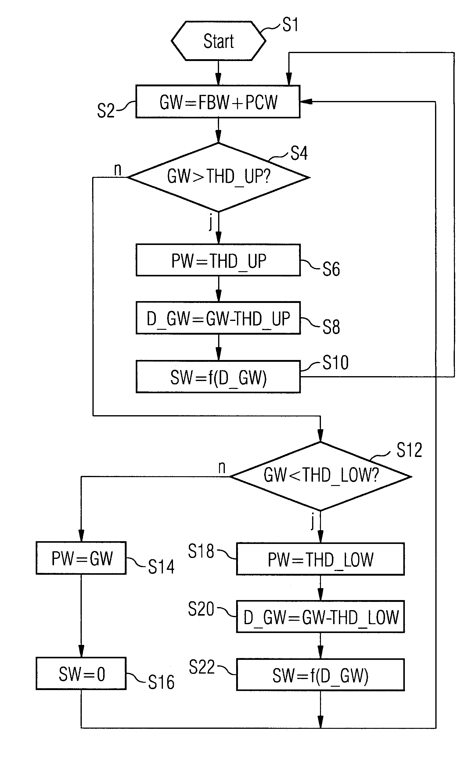
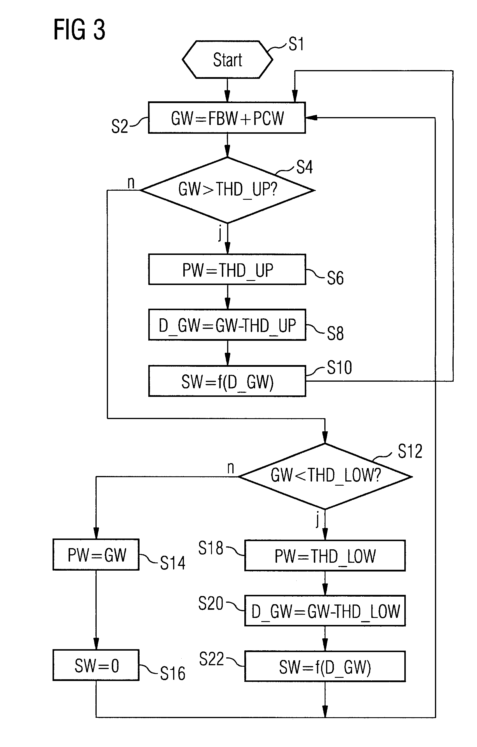
[0048]the program for the manipulated variable splitting unit 49 is started in a step S1 (FIG. 3) in which variables are preferably initialized.

[0049]In a step S2 a total value GW of the primary manipulated variable is determined by summing the regulator value FBW and of the pilot control value PCW. Alternatively just the regulator value or values FBW can be assigned to the total value GW. Thus the total value GW can be determined if both a cylinder-specific Lambda regulator and an uneven running regulator which each form the regulator 47 by forming the sum of the respective regulator values FBW and possibly the pilot control value PCW are present.

[0050]In a step S4 a check is subsequently performed as to whether the total value GW is greater than an upper threshold value THD_UP. If the condition of step S4 is fulfilled, the upper threshold value THD_UP is assigned to the primary value PW of the primary manipulated variable in the step S6. In a step S8 a residual value D_GW is deter...

second embodiment

[0055]the program is explained in greater detail below with reference to FIGS. 4 and 5. The program is started in a step S24 in which variables are initialized where necessary. In a step S26 the total value, as in step S2, is assigned the regulator value FBW and the pilot control value PC and where necessary the pilot control value PCW. In a step S28 a check is subsequently performed as to whether the total value GW is greater than the upper threshold value THD_UP.

[0056]If it is, in a step S30 a first marker M_UP is set to a value of TRUE. Subsequently in a step S32, the primary value PW is assigned the upper threshold value THD_UP. Furthermore in a step S34 the residual value D_GW is determined by forming the difference between the total value GW and the upper threshold value THD_UP.

[0057]In a step S36 the secondary value SW is determined as a function of the residual value D_GW and an increment value EHW. The increment value can for example be fixed beforehand or also be embodied ...


PUM


Abstract

Injectors each having a piezo actuator are assigned to cylinders of an internal combustion engine. A regulator device is configured for furnishing a cylinder-specific controlled variable and a command variable to a controller whose primary manipulated variable is a variable representing an electrical power supplied to the piezo actuator during a control cycle. A manipulated variable splitting unit is provided whose input variable is a regulator-determined regulator value of the primary manipulated variable and is configured for determining a total value of the primary manipulated variable according to the regulator value. It is also configured for splitting the total value into a primary value of the primary manipulated variable and into a secondary value of a secondary manipulated variable according to a lower and / or upper threshold value of the total value.

Description

CROSS REFERENCE TO RELATED APPLICATIONS[0001]This application is the U.S. National Stage of International Application No. PCT / EP2006 / 060305, filed Feb. 27, 2006 and claims the benefit thereof. The International Application claims the benefits of German application No. 10 2005 010 028.7 filed Mar. 4, 2005, both of the applications are incorporated by reference herein in their entirety.FIELD OF INVENTION[0002]The invention relates to a regulator device for compensating for dispersions of injectors, each having a piezo actuator, which is assigned to cylinders of an internal combustion engine.BACKGROUND OF THE INVENTION[0003]Internal combustion engines are increasingly equipped with injectors to which piezo actuators are assigned as adjustment drives. These types of injector have the advantage that very short valve opening times of the injectors can be achieved with them and thus a number of part injections are possible during one operating cycle of a cylinder of the internal combustion...

Claims


Application Information

Patent Timeline
Patent Type & Authority Patents(United States)
IPC IPC(8): F02D41/14F02D41/20
CPCF02D41/0085F02D41/2096F02D2041/2048F02D41/1498
Inventor ALIAKBARZADEH, REZAJOACHIMSMEYER, DIRK
Owner VITESCO TECH GERMANY GMBH
Learn More