Gas-streaming slag collecting device

A technology for collecting slag and gas supply pipes, which is applied in the field of metallurgy, can solve the problems that the gas injection port cannot be adjusted in the circumferential direction, the scum cannot be completely removed, and the operation platform is time-consuming and labor-intensive, so as to avoid the pollution of the environment by the smoke overflow and realize the removal time , cost-saving effect

Active Publication Date: 2018-11-13
PANZHIHUA IRON & STEEL RES INST OF PANGANG GROUP
View PDF6 Cites 4 Cited by
  • Summary
  • Abstract
  • Description
  • Claims
  • Application Information

AI Technical Summary

Problems solved by technology

[0004] Existing slag gathering devices mainly include horizontal, vertical and oblique insertion types, some of which use single-gun air injection, and some of which use symmetrical double-air injection guns. No matter which method is used, there are the following disadvantages: (1) The volume is very large, It can only be used in slag-picking places with ample space
The problem with the above-mentioned technical solution is that, with the use of double-gun air injection, there is a blind area of ​​interference in the surge area, and scum is easily retained and cannot be completely removed; in addition, the double-pipe air consumption is greater, which increases the cost
The problems in the above-mentioned technical scheme are: 1. The air spray gun can only move up and down relative to the ladle along the length direction of the air spray gun, but cannot adjust the position of the air injection port in the circumferential direction. liquid surface, it is difficult to gather the residue together; 2. It is time-consuming and labor-intensive to build the operation platform and takes up a lot of space

Method used


Image

  • Gas-streaming slag collecting device
  • Gas-streaming slag collecting device
  • Gas-streaming slag collecting device

Examples


Embodiment Construction

[0024] The present invention will be further described below in conjunction with the accompanying drawings.

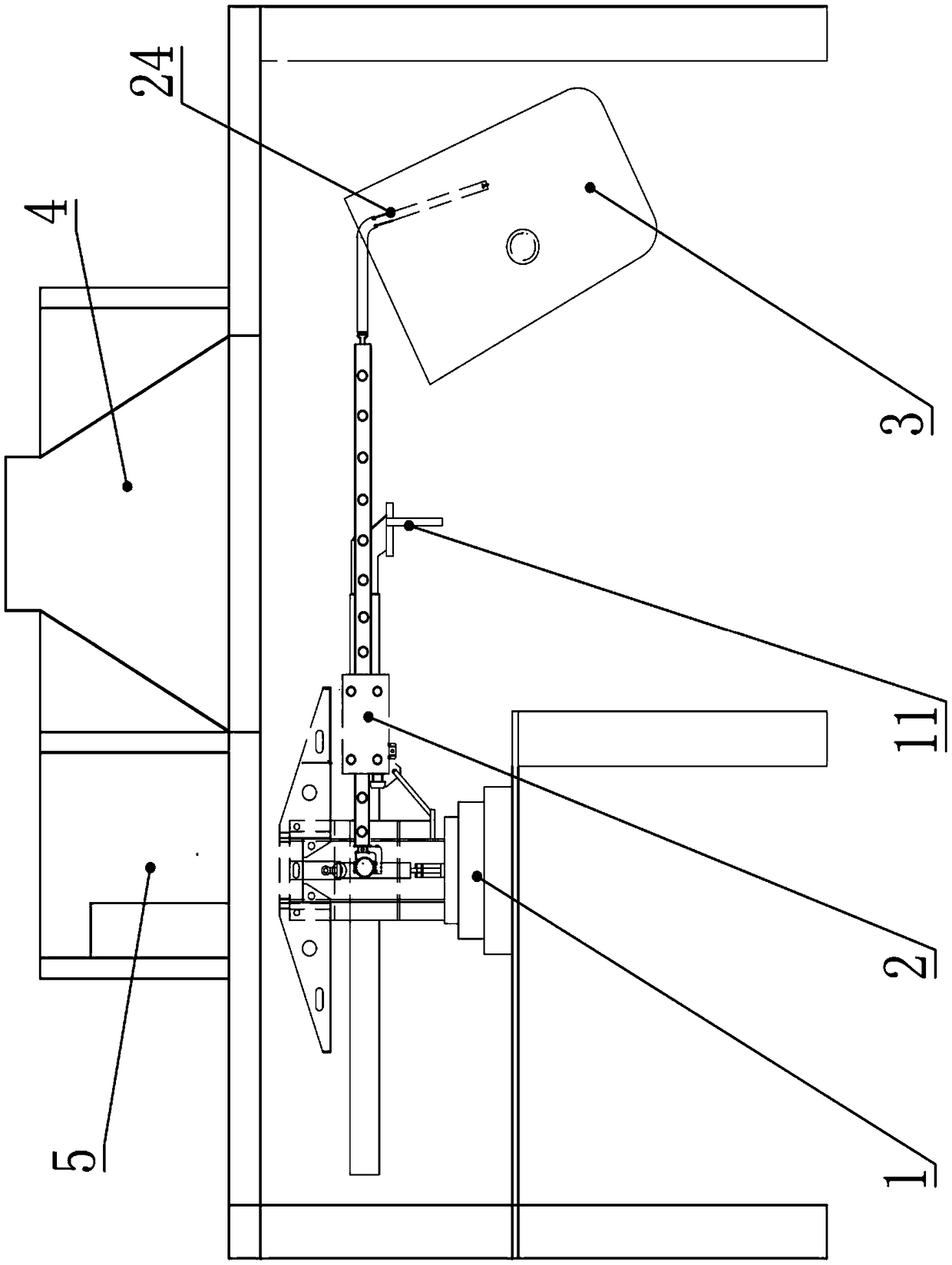
[0025] Such as Figure 1 to Figure 4 As shown, the air surge slag gathering device of the present invention includes a slag removal machine 1 and a slag collection device 2. The slag removal machine 1 is arranged on a horizontal workbench, and the slag removal machine 1 and the slag collection device 2 are detachably connected without additional construction. The slag gathering device 2 is placed on the workbench, which occupies a small space;

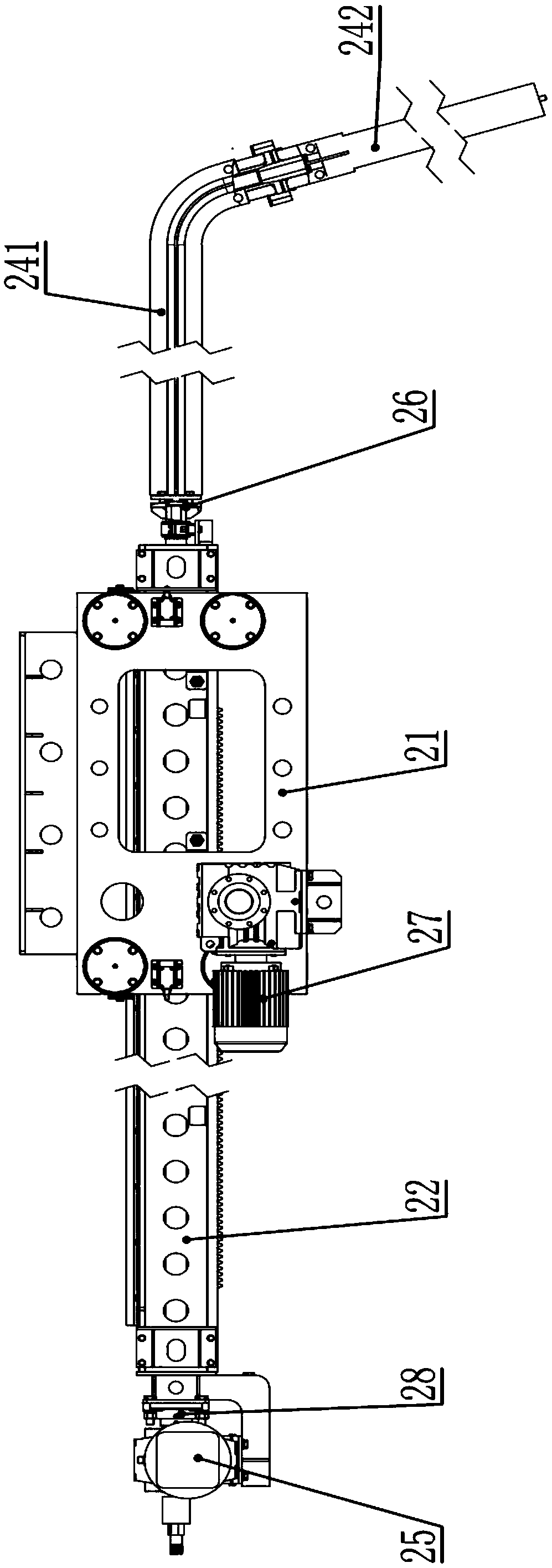
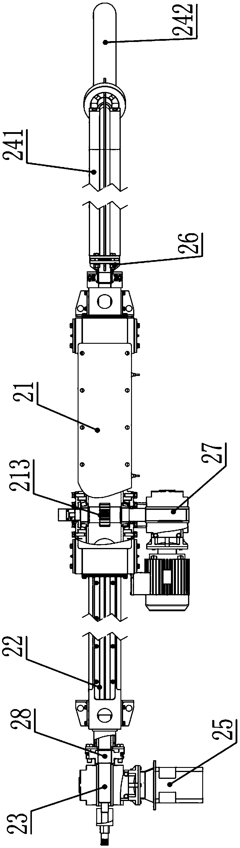
[0026] The slag gathering device 2 comprises a gear box 21, a rack box 22, an air supply pipe 23, an air spray gun 24, and a servo motor 25. The rack box 22 is in the shape of a strip, and the center of the bottom of the rack box 22 is provided with a rack along the length direction. The rack box 22 is driven by the gear box 21, and the rack box 22 can pass through the gear box 21 to reciprocate in the horizontal direction; th...


PUM


Abstract

The invention relates to the technical field of metallurgy and particularly relates to a gas-streaming slag collecting device. The gas-streaming slag collecting device comprises a slagging-off machineand a slag collecting device; the slag collecting device comprises a gearbox, a rack box, a gas supply pipe, a gas spraying gun and a servo motor; the rack box is driven by the gearbox; the rack boxcan do reciprocating motion in the horizontal direction after penetrating through the gearbox; the gas supply pipe is arranged inside the rack box; one end of the gas supply pipe is connected with thegas spraying gun through a rotary joint A; the servo motor is installed on the rack box; the servo motor is connected with the gas supply pipe and can be used for driving the gas supply pipe to rotate relative to the rack box; and the gas spraying gun is provided with a gas pipe which communicates with the gas supply pipe. The gas-streaming slag collecting device provided by the invention is small in space usage and can realize a steaming slagging-off process at all slagging-off sites; the gas spraying gun can rotate 360 degrees in the circumferential direction along with the gas supply pipe;in a gas-spray streaming process, the position and the depth of a spraying and blowing point can be controlled in real time; the slagging-off time, the temperature reduction of molten steel and gas consumption amount can be optimized; and thus the slagging-off cost is minimized.

Description

technical field [0001] The invention relates to the technical field of metallurgy, in particular to an air surge slag gathering device for removing scum in a ladle after desulfurization. Background technique [0002] After the molten iron is desulfurized, the scum on the surface of the molten steel must be removed in time. This is because the sulfur content in the residue is high and will diffuse into the molten steel, causing the phenomenon of "returning sulfur" in the converter, which will greatly increase the cost of refining and desulfurization in the subsequent process. Practice has proved that half of the composition of desulfurization slag removed is iron, which shows that the iron loss caused by the slag removal process is relatively large, resulting in the repeated use of slag accumulators; in addition, the slag removal time is longer and the temperature drop is larger , resulting in higher cost of the traditional slag removal method. [0003] At present, some ente...

Claims


Application Information

Patent Timeline
Patent Type & Authority Applications(China)
IPC IPC(8): C21C7/072B22D43/00
CPCB22D43/007C21C7/072
Inventor 彭宏亮庞兴利贾子松梁新腾李扬洲
Owner PANZHIHUA IRON & STEEL RES INST OF PANGANG GROUP
Why Eureka
Try Eureka