Seat cushion

a seat cushion and seat technology, applied in the field of seat cushions, can solve the problems of increasing the discomfort of sitting, adding to the discomfort of thermal and sweating, and the weight of prior seat cushions, when made from rubber, and being difficult to transport, so as to achieve the optimal mix of rigidity and flexibility

Inactive Publication Date: 2010-04-13
BACKJOY ORTHOTICS
View PDF68 Cites 33 Cited by
  • Summary
  • Abstract
  • Description
  • Claims
  • Application Information

AI Technical Summary

Benefits of technology

[0008]The percentages of the EVA, rubber and / or additional materials are significant for the compositions of the body and the spacing members for achieving an optimal mix of rigidity and flexibility for support and comfort of use.
[0013]In another embodiment, the plurality of spacing members are sized in length in the first direction and sized in cross-sectional area orthogonal to the length, in combination with the composition, to substantially support the body without significant flexing of the spacing members or body.

Problems solved by technology

Sporting and entertainment facilities typically provide seating areas including one or more sections of solid surface seating, such as benches or bleachers, that are hard and uncomfortable to sit on for extended seating periods.
Accordingly, on particularly hot or cold days, for example, such benches or bleachers may add to seating discomfort by transmitting the cold or heat directly to a person's posterior.
Such cushions, while softening the seating surface over that of a solid surface, substantially block air flow to the person's posterior, thereby adding to the person's thermal and sweating discomfort.
In addition, prior seat cushions, when made from rubber, are heavy are not easy to transport from, for example the trunk of the user's automobile, to a stadium seat.
Further, when made from a foam, the seat cushion may not have a sufficient level of rigidity to support the user without bending or collapsing the seat cushion structure.
Moreover, prior seat cushions were not easy to clean, to remove stains or the smell of beverages which may have spilled on such prior seat cushions.

Method used


Image

  • Seat cushion
  • Seat cushion
  • Seat cushion

Examples


Embodiment Construction

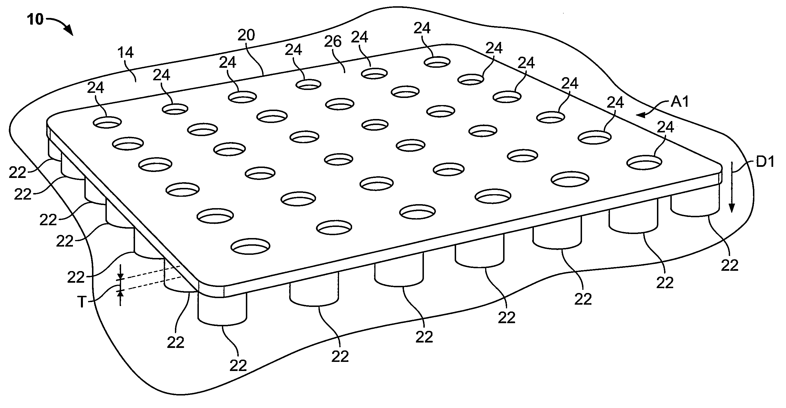
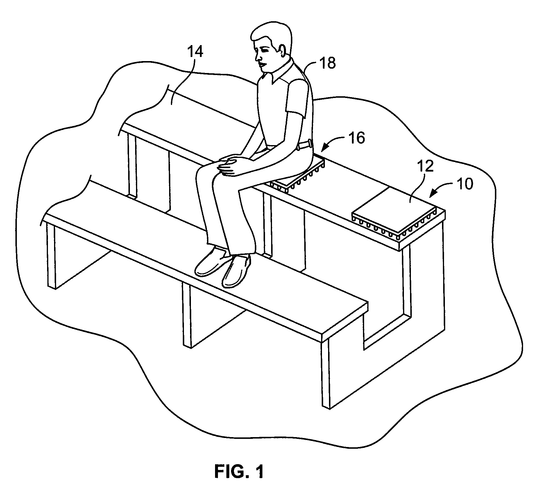
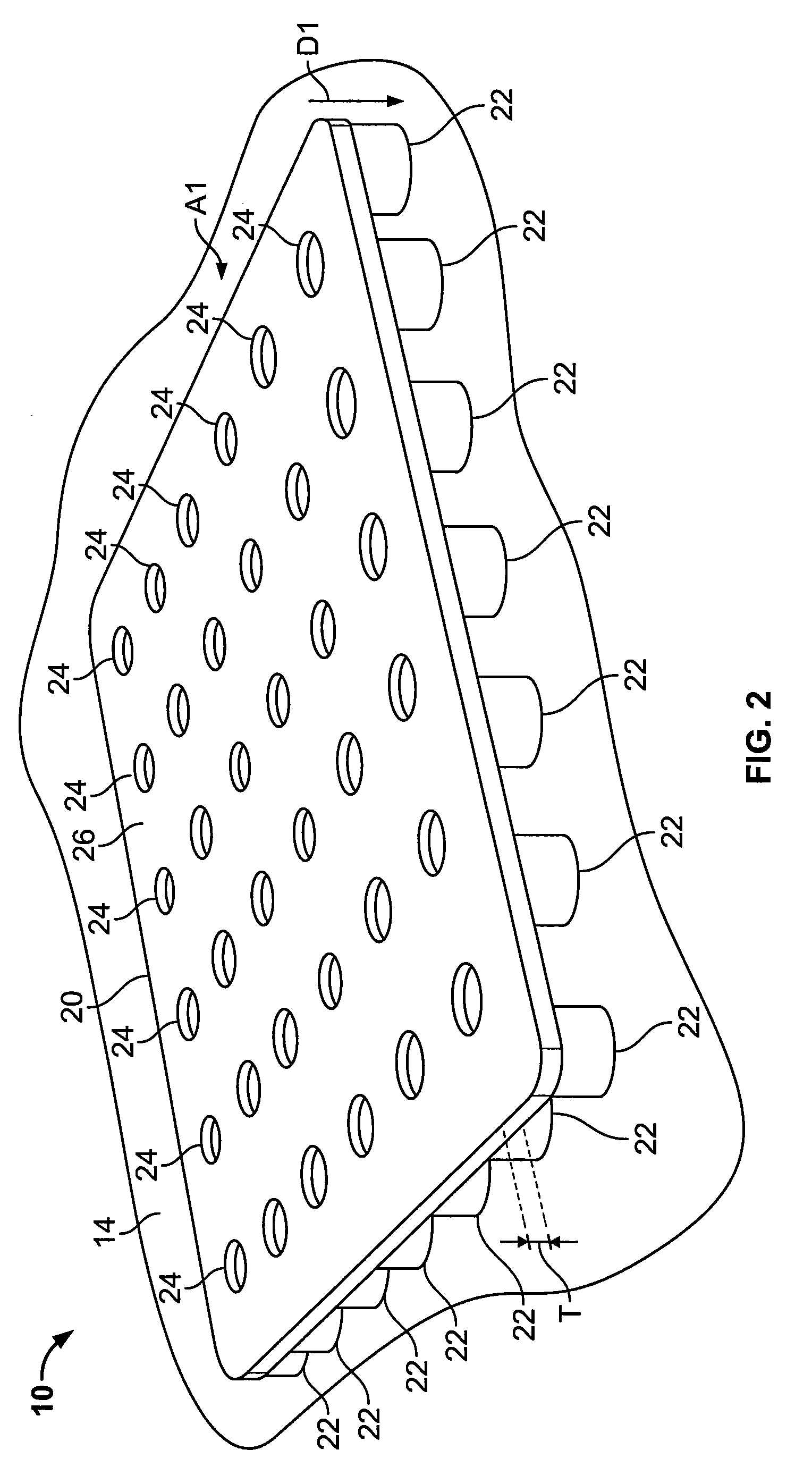
[0040]FIG. 1 is a perspective view showing a seat cushion 10, which is configured in accordance with the various embodiments of the present invention. In FIG. 1, seat cushion 10 is fitted with an optional fabric cover 12. Seat cushion 10 may be positioned directly on a sitting surface 14, such as for example, to be used in portable stadium-events seating, such as a stadium or arena bleacher. Other uses of seat cushion 10 include, for example: placement of seat cushion 10 on the seat of a motorized vehicle, e.g., an auto, motorcycle, tractor, etc; on the ground, for example to be used for outdoor music or sporting events; and on seating surfaces in, for example, homes, commercial sites, e.g., shopping malls, industrial sites, e.g., factories, offices, etc. Other examples of the use of the seat cushion can include more permanent settings, such as for example being incorporated into the structural design of stadium seating, office furniture, automobile seating, boating industry seating...


PUM


Abstract

A seat cushion having a flexible and semi-rigid body is provided. The body has a seating surface, having a first area, and a support surface, having a second area, spaced apart from the seating surface forming a body thickness. The body has a body composition with a first percentage by volume of EVA (Ethyl Vinyl Acetate), substantially evenly mixed with additional materials, such as polyethylene, color pigment, polycarbonate, and / or dicumyl peroxide, in various percentages of the body composition. The seat cushion also has a plurality of spacing members spaced apart and substantially evenly distributed across the second area. The plurality of spacing members each have a spacing member composition with a second percentage by volume of EVA and with a third percentage by volume of rubber. The seat cushion further has a plurality of ventilation holes extending through the body from the seating surface to the support surface.

Description

CROSS REFERENCE TO RELATED APPLICATIONS[0001]This application claims priority from and is a continuation-in-part of U.S. patent application Ser. No. 11 / 489,010, entitled “Seat Cushion,” filed on Jul. 19, 2006, and claims priority from U.S. Patent Application Ser. No. 60 / 916,217, entitled “Seat Cushion,”filed May 4, 2007, both of which are incorporated herein by reference.TECHNICAL FIELD[0002]The present invention relates to human seating comfort, and, more particularly, to a seat cushion, with at least improved stability, durability, comfort, and ease of transport.BACKGROUND[0003]Sporting and entertainment facilities typically provide seating areas including one or more sections of solid surface seating, such as benches or bleachers, that are hard and uncomfortable to sit on for extended seating periods. Such solid surface seating, for example, may be made from metal or wood, and may be thermally conductive. Accordingly, on particularly hot or cold days, for example, such benches or...

Claims


Application Information

Patent Timeline
Patent Type & Authority Patents(United States)
IPC IPC(8): A47C7/02
CPCA47C7/74A47C7/021
Inventor PRUST, PETER C.
Owner BACKJOY ORTHOTICS
Why Eureka
Try Eureka