
Gerotor apparatus for a quasi-isothermal Brayton cycle engine

a cycle engine and gearbox technology, applied in the direction of positive displacement liquid engines, liquid fuel engines, piston pumps, etc., can solve the problems of difficult to achieve perfect erickson cycles, low power density, and low efficiency of otto cycle engines, so as to improve fluid intake and reduce engine dead volume. effect of engine system

Active Publication Date: 2010-04-13
TEXAS A&M UNIVERSITY +1
View PDF125 Cites 20 Cited by
  • Summary
  • Abstract
  • Description
  • Claims
  • Application Information

AI Technical Summary

Benefits of technology

The invention is an engine system with a housing, outer gerotor, inner gerotor, tip inlet port, face inlet port, and tip outlet port. The technical effects of the invention include enhanced fluid intake, reduced dead volume, selective fluid passage, temperature manipulation, abrasion of outer gerotor tips, adjustment of compression or expansion ratio, creation of symmetries to balance pressures, and creating a journal bearing. The invention also allows for the use of a motor embedded in the inner or outer gerotor.

Problems solved by technology

The Otto Cycle engine is an inexpensive, internal combustion, low-compression engine with a fairly low efficiency.
In practice, a perfect Erickson cycle is difficult to achieve because isothermal expansion and compression are not readily attained in large, industrial equipment.
It features low power density, mechanical complexity, and difficult-to-achieve constant-temperature compressor and expander.
It has a higher power density than the Carnot cycle, but it is difficult to perform the heat exchange, and it is difficult to achieve constant-temperature compression and expansion.
In practice, real engines have “irreversibilities,” or losses, associated with friction and temperature / pressure gradients.
These devices are generally suitable for aviation in which aircraft operate at fairly constant speeds; they are generally not suitable for most transportation applications, such as automobiles, buses, trucks, and trains, which must operate over widely varying speeds.
Further, the Otto and Diesel cycle engines lose efficiency because they do not completely expand high-pressure gases, and simply throttle the waste gases to the atmosphere.

Method used


Image

  • Gerotor apparatus for a quasi-isothermal Brayton cycle engine
  • Gerotor apparatus for a quasi-isothermal Brayton cycle engine
  • Gerotor apparatus for a quasi-isothermal Brayton cycle engine

Examples


Embodiment Construction

[0051]It should be understood at the outset that although example embodiments of the present invention are illustrated below, the present invention may be implemented using any number of techniques, whether currently known or in existence. The present invention should in no way be limited to the example embodiments, drawings, and techniques illustrated below, including the embodiments and implementation illustrated and described herein. Additionally, the drawings are not necessarily drawn to scale.

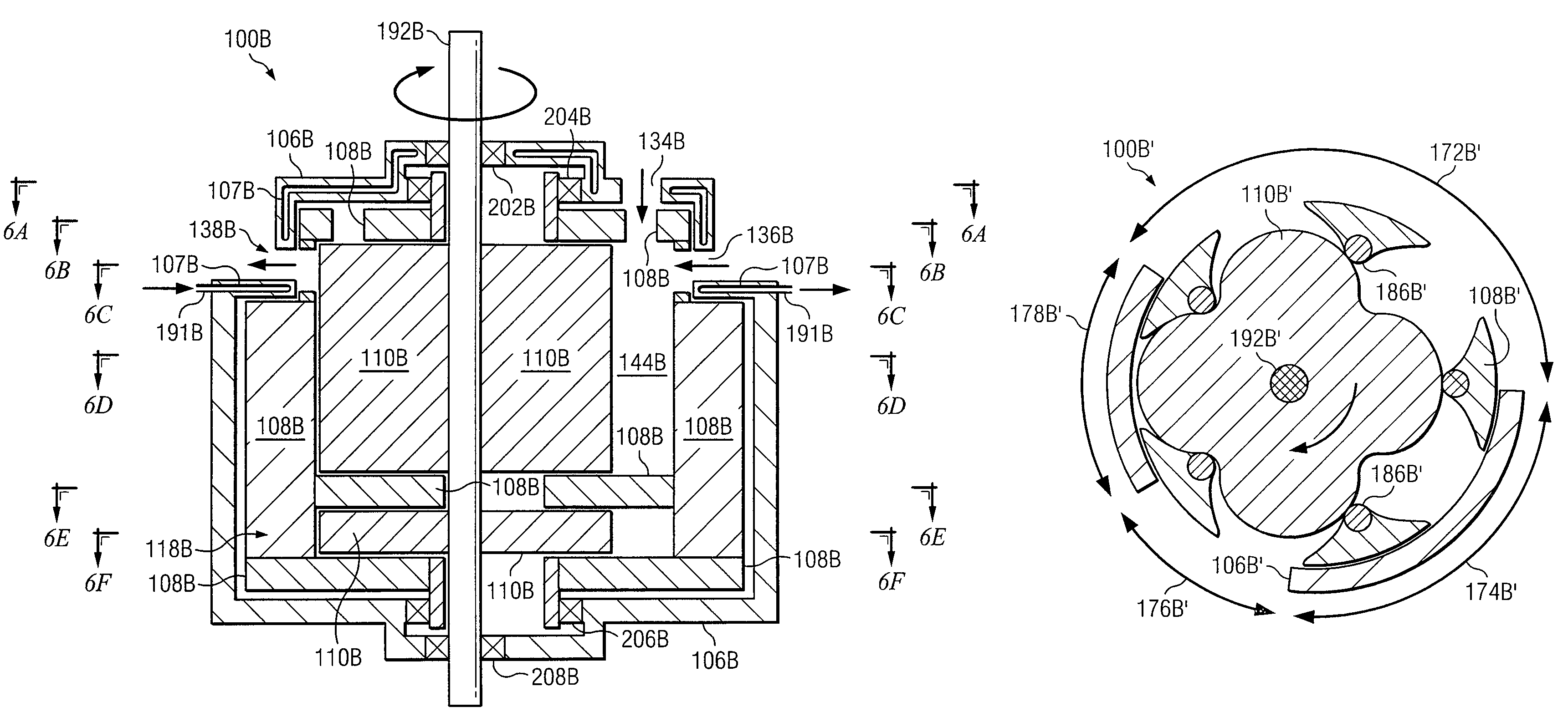
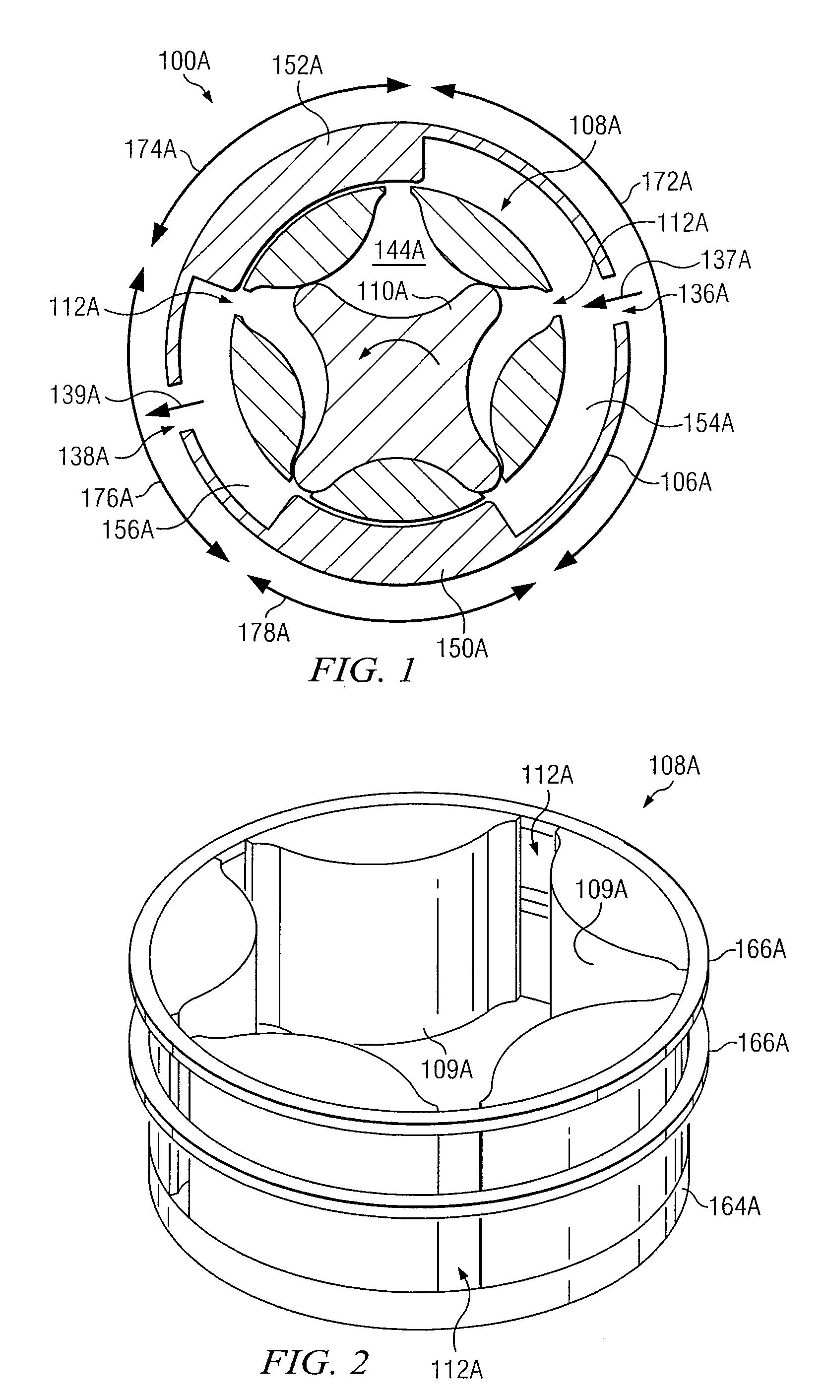
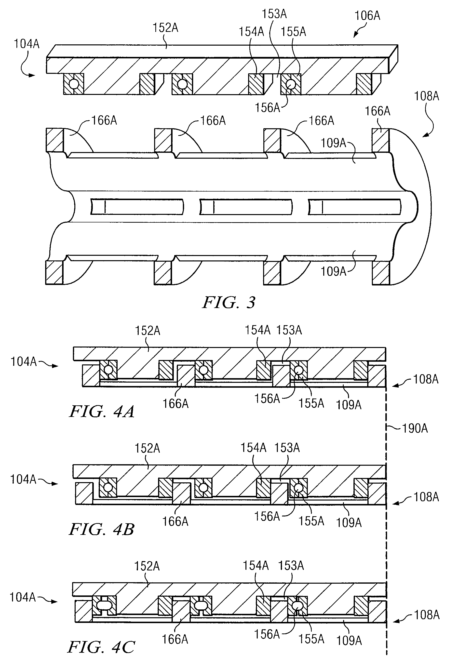
[0052]FIGS. 1 through 22 below illustrate example embodiments of engine systems within the teachings of the present invention. Although the detailed description will describe these engine systems as being used in the context of a gerotor compressor, some of the engine system may function equally as well as gerotor expanders and / or combinations of gerotor expanders and compressors. In addition, the present invention contemplates that the engine systems described below may be utilized in any...


PUM


Abstract

According to one embodiment of the invention, an engine system comprises a housing, an outer gerotor, an inner gerotor, a tip inlet port, a face inlet port, and a tip outlet port. The housing has a first sidewall, a second sidewall, a first endwall, and a second endwall. The outer gerotor is at least partially disposed in the housing and at least partially defines an outer gerotor chamber. The inner gerotor is at least partially disposed within the outer gerotor chamber. The tip inlet port is formed in the first sidewall and allows fluid to enter the outer gerotor chamber. The face inlet port is formed in the first endwall and allows fluid to enter the outer gerotor chamber. The tip outlet port is formed in the second sidewall and allows fluid to exit the outer gerotor chamber.

Description

RELATED APPLICATIONS[0001]Pursuant to 35 U.S.C. §119 (e), this application claims priority to U.S. Provisional Patent Application Ser. No. 60 / 621,221, entitled QUASI-ISOTHERMAL BRAYTON CYCLE ENGINE, filed Oct. 22, 2004. U.S. Provisional Patent Application Ser. No. 60 / 621,221 is hereby incorporated by reference.TECHNICAL FIELD OF THE INVENTION[0002]The present invention relates to a gerotor apparatus that functions as a compressor or expander. The gerotor apparatus may be applied generally to Brayton cycle engines and, more particularly, to a quasi-isothermal Brayton cycle engine.BACKGROUND OF THE INVENTION[0003]For mobile applications, such as an automobile or truck, it is generally desirable to use a heat engine that has the following characteristics: internal combustion to reduce the need for heat exchangers; complete expansion for improved efficiency; isothermal compression and expansion; high power density; high-temperature expansion for high efficiency; ability to efficiently “...

Claims


Application Information

Patent Timeline
Patent Type & Authority Patents(United States)
IPC IPC(8): F01C19/00F03C2/00
CPCF01C1/103F01C21/06F01C20/14F01C19/02F01C1/10F01C11/00F01C17/02F02C5/00F01C1/104
Inventor HOLTZAPPLE, MARK T.RABROKER, ANDREWROSS, MICHAEL KYLEATMUR, STEVEN D.NOYES, GARY P.
Owner TEXAS A&M UNIVERSITY
Learn More