
Controlled vapor deposition of biocompatible coatings over surface-treated substrates

a biocompatible coating and surface treatment technology, applied in the field of surface treatment of substrates, can solve the problems of limited control over the surface properties of applied coatings, limited device yield, and limited use of liquid phase processing, so as to achieve more hydrophilic and compatible bonding of peg layers to hydrophobic surfaces, the effect of increasing the hydrophilicity

Active Publication Date: 2010-04-13
SPTS TECH LTD
View PDF31 Cites 30 Cited by
  • Summary
  • Abstract
  • Description
  • Claims
  • Application Information

AI Technical Summary

Benefits of technology

[0059]With reference to the application of chlorosilane-based coating systems of the kind described in the Background Art section of this application, for example, and not by way of limitation, the degree of hydrophobicity of the substrate after deposition of an oxide bonding layer and after deposition of an overlying silane-based polymeric coating can be uniformly controlled over the substrate surface. By controlling a deposited bonding layer (for example) surface coverage and roughness in a uniform manner (as a function of oxide deposition parameters described above, for example and not by way of limitation), we are able to control the concentration of OH reactive species on the substrate surface. This, in turn, controls the density of reaction sites needed for subsequent deposition of a silane-based polymeric coating. Control of the substrate surface active site density enables uniform growth and application of high density self-aligned monolayer coatings (SAMS), for example.
[0060]By controlling the total pressure in the vacuum processing chamber, the number and kind of vaporous components charged to the process chamber, the partial pressure of each vaporous component, the substrate temperature, the temperature of the process chamber walls, and the time over which particular conditions are maintained, the chemical reactivity and properties of the coating can be controlled. By controlling the process parameters, density of film coverage over the substrate surface; chemistry-dependent structural composition; film thickness; and film uniformity over the substrate surface are more accurately controlled. Chemistry-dependent structural composition is most frequently generated by use of a combination of layers, where different layers have a different chemical composition. Control over process parameters makes possible the formation of very smooth films, with RMS roughness which typically ranges from about 0.1 nm to less than about 15 nm, and even more typically from about 1 nm to about 5 nm. For oxide films used to provide a hydrophilic surface, and / or used as a bonding layer, the thickness of the oxide film typically ranges from about 1 nm (10 Å) to about 20 nm. Oxide films thicker than 20 nm (up to about 500 nm) are used when mechanical properties and film abrasion resistance are of particular importance. These films can be tailored in thickness, roughness, and density, which makes them particularly well suited for applications in the field of biotechnology and electronics and as bonding layers for various functional coatings in general.
[0068]Although just one layer of PEO / PEG may be applied, when it is desired to increase the thickness of the PEO / PEG layer, step c) can be repeated. Typically, the PEO / PEG precursor may be charged to the reactor chamber and then pumped down to remove byproduct and unreacted precursor material in a series of steps to increase deposited layer thickness. A series of the charge and pump down steps in the range of about 2 to about 10 is common, with a range of about 4 to about 8 being more common. Application of a series of add-on layers to increase the total thickness of the deposited PEO / PEG layer improves the uniformity of the deposited PEO / PEG layer over the surface of the substrate. It is not necessary to plasma treat the surface of the existing PEO / PEG layer prior to charging additional reactant for deposition, since the surface of the existing PEO / PEG layer is easily bonded to by the newly charged PEO / PEG layer precursor material.
[0071]Oxide / polyethylene glycol (PEG) coatings providing hydrophilicity can also be deposited, using the present method, over the surfaces of various medical devices and implants, which are intended for various time periods of use. Internal devices such as smart bio-chips, which may include internal diagnostic devices are excellent applications for coated structures. External devices such as contact lenses, external diagnostic devices (including microfluidic devices), and catheters, for example, provide excellent applications for coated structures. Coated structures which are intended for “permanent” (i.e., at least 5 to 10 years) implantation within the body may include devices such as intra-ocular lenses, synthetic blood vessels and heart valves, stents, joint (such as a hip or knee) or hard tissue (i.e., bone or cartilage) replacements, and breast implants, for example and without limitation. The application of a hydrophilic oxide / PEG coating over surfaces of the medical device or implant improves both the hydrophilicity and biocompatibility.
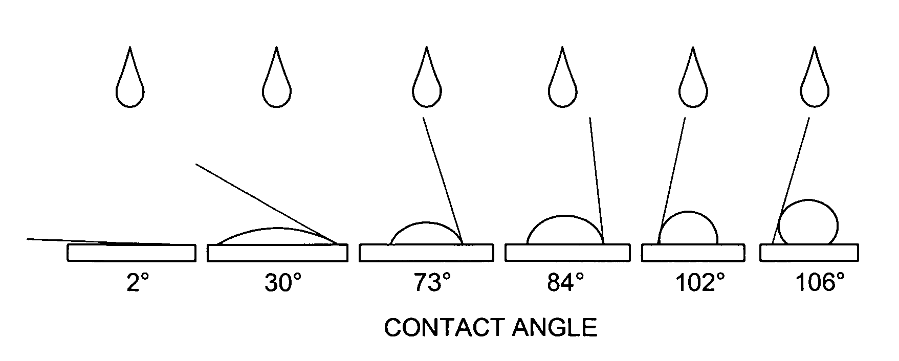
[0073]The bonding of the PEG layer to a hydrophobic surface is improved when the surface has been treated with UV radiation in the presence of oxygen or ozone, to render the surface more hydrophilic and more compatible with PEG. The data presently available to us indicates that we have not yet been able to cover the entire surface of the treated substrate with PEG. A treated surface which is entirely covered with PEG should maintain the 6° contact angle unless the PEG layer is damaged so that underlying substrate is exposed.

Problems solved by technology

While this technique enables efficient coating deposition, it frequently results in limited control over the surface properties of the applied coating.
In the case of coating a surface of a medical device which must function on a nanometer scale, use of liquid phase processing limits device yield due to contamination and capillary forces.
However, the common vapor-phase deposition methods may not permit sufficient control of the molecular level reactions taking place during the deposition of surface bonding layers or during the deposition of functional coatings, when the deposited coating needs to exhibit functional surface properties on a nanometer (nm) scale.
(Abstract) The introduction of the article explains that bone and dental implant technology is currently inadequate.
The bond between bone and implant materials (such as Ti and metal alloys) is said to fail, requiring additional surgery to remove and replace the implant after only a few years of use.
Too small an RMS surface is said to result in the surface being too smooth, that is to say an insufficient increase in the surface area / or insufficient depth of the surface peaks and valleys on the surface.
However, too great an RMS surface area is said to result in large surface peaks, widely spaced apart, which begins to diminish the desirable surface area for subsequent reaction with the chloroalkylsilane by vapor deposition.
These aggregates are said to clog or mask micro / nano-size features on devices.
This hydrophobicity is described as resulting in poor wettability with aqueous solvents, which renders microchannel devices susceptible to the trapping of air bubbles, and makes the surfaces of the microchannels prone to nonspecific adsorption to proteins and cells.
However, upon reading these informative descriptions, it becomes readily apparent that control of coating deposition on a molecular level is not addressed in adequate detail in most instances.
Without precise control of the deposition process, the coating may lack thickness uniformity and surface coverage, providing a rough surface.
Any one of these non-uniformities may result in functional discontinuities and defects on the coated substrate surface which are unacceptable for the intended application of the coated substrate.

Method used


Image

  • Controlled vapor deposition of biocompatible coatings over surface-treated substrates
  • Controlled vapor deposition of biocompatible coatings over surface-treated substrates
  • Controlled vapor deposition of biocompatible coatings over surface-treated substrates

Examples


example one

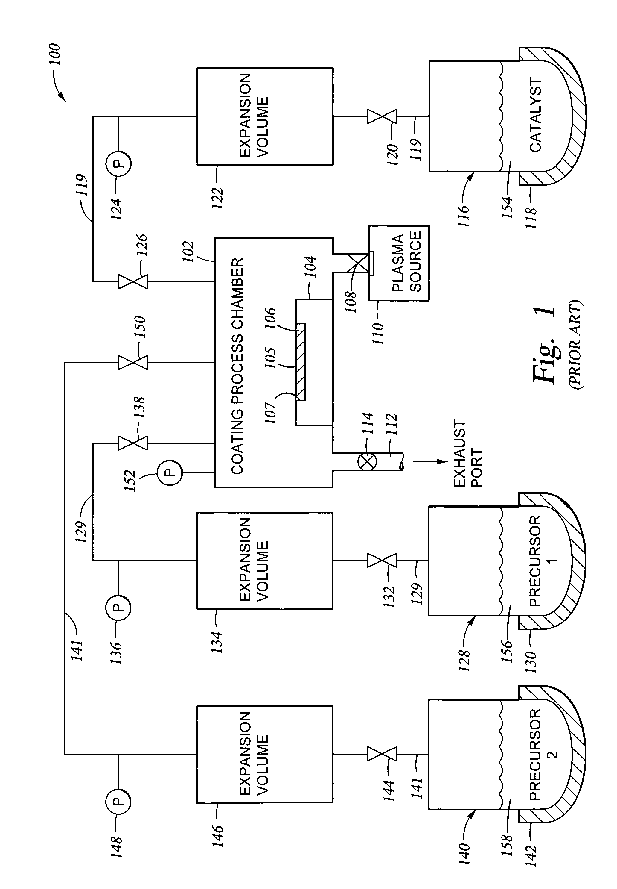
[0121]The vapor deposition techniques described previously herein were used to coat devices such as implantable (intraocular) lenses with a hydrophilic oxide / polyethylene glycol coating. Prior to deposition of the coating, the device surface was pre-treated by exposure to an oxygen plasma (150-200 sccm O2 at an RF power of about 200 W and a process chamber pressure of 0.3 Torr in an Applied MicroStructures' MVD™ process chamber) for 5 minutes in order to clean the surface and create hydroxyl availability on a substrate surface (by way of example and not by way of limitation).

[0122]Following oxygen plasma treatment of the lens, SiCl4 was charged to the process chamber from a SiCl4 vapor reservoir, where the SiCl4 vapor pressure in the vapor reservoir was 18 Torr, creating a partial pressure of 2.3 Torr in the coating process chamber. Within 5 seconds, a first volume of H2O vapor was charged to the process chamber from a H2O vapor reservoir, where the H2O vapor pressure in the vapor r...

example two

[0159]Deposition of a Silicon Oxide Layer Having a Controlled Number of OH Reactive Sites Available on the Oxide Layer Surface

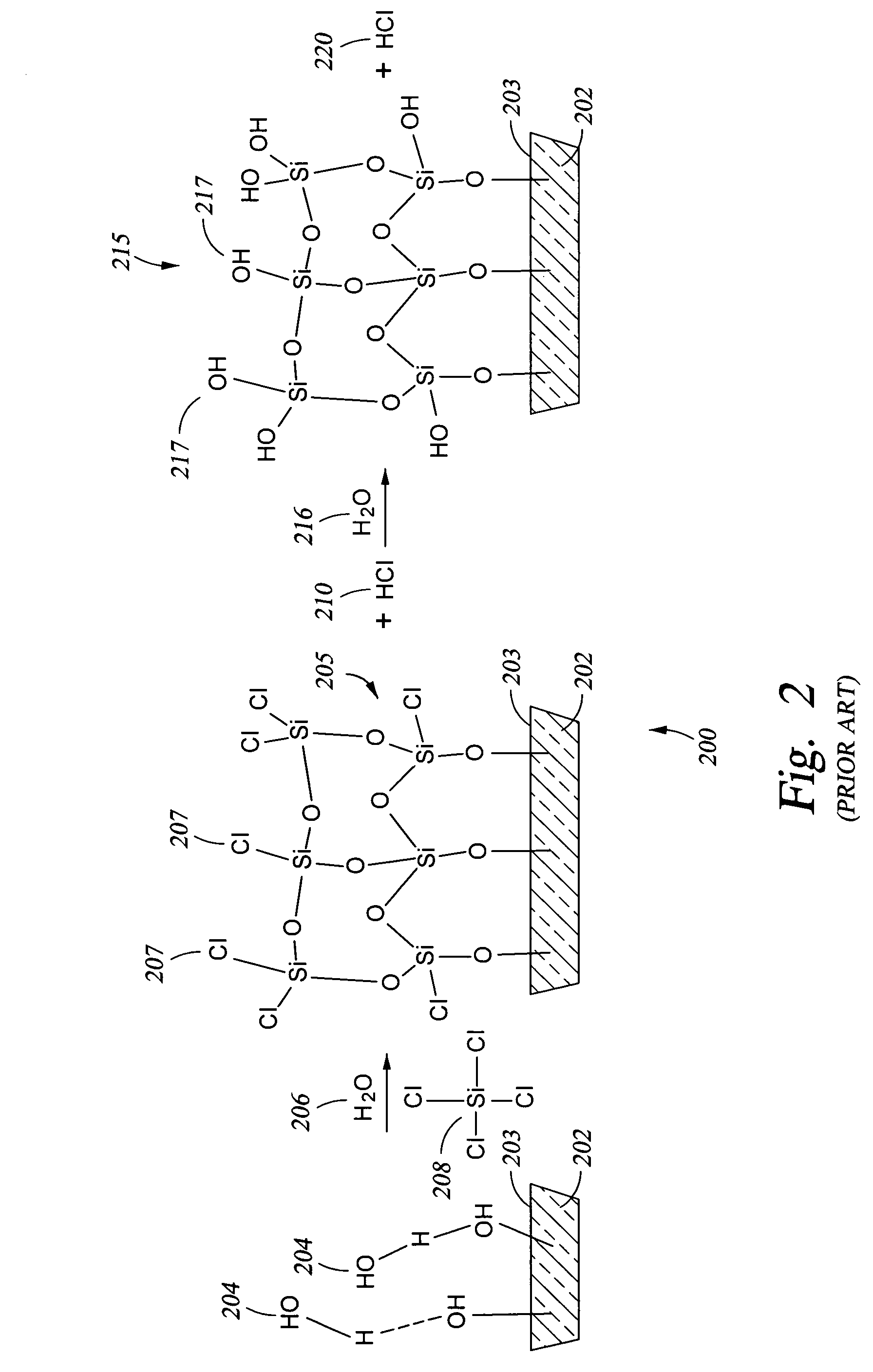
[0160]A technique for adjusting the hydrophobicity / hydrophilicity of a substrate surface (so that the surface is converted from hydrophobic to hydrophilic or so that a hydrophilic surface is made more hydrophilic, for example) may also be viewed as adjusting the number of OH reactive sites available on the surface of the substrate. One such technique is to apply an oxide coating over the substrate surface while providing the desired concentration of OH reactive sites available on the oxide surface. A schematic 200 of the mechanism of oxide formation in shown in FIG. 2. In particular, a substrate 202 has OH groups 204 present on the substrate surface 203. A chlorosilane 208, such as the tetrachlorosilane shown, and water 206 are reacted with the OH groups 204, either simultaneously or in sequence, to produce the oxide layer 205 shown on surface 203 of substrat...

example three

[0162]In the preferred embodiment discussed below, the silicon oxide coating was applied over a glass substrate. The glass substrate was treated with an oxygen plasma in the presence of residual moisture which was present in the process chamber (after pump down of the chamber to about 20 mTorr) to provide a clean surface (free from organic contaminants) and to provide the initial OH groups on the glass surface.

[0163]Various process conditions for the subsequent reaction of the OH groups on the glass surface with vaporous tetrachlorosilane and water are provided below in Table 2, along with data related to the thickness and roughness of the oxide coating obtained and the contact angle (indicating hydrophobicity / hydrophilicity) obtained under the respective process conditions. A lower contact angle indicates increased hydrophilicity and an increase in the number of available OH groups on the silicon oxide surface.

[0164]

TABLE 2Deposition of a Silicon Oxide Layer of Varying Hydrophilici...


PUM

PropertyMeasurementUnit
contact angleaaaaaaaaaa
wavelengthaaaaaaaaaa

Abstract

We have developed an improved vapor-phase deposition method and apparatus for the application of layers and coatings on various substrates. The method and apparatus are useful in the fabrication of biofunctional devices, Bio-MEMS devices, and in the fabrication of microfluidic devices for biological applications. In one important embodiment, a siloxane substrate surface is treated using a combination of ozone and UV radiation to render the siloxane surface more hydrophilic, and subsequently a functional coating is applied in-situ over the treated surface of the siloxane substrate.

Description

[0001]This application is a continuation-in-part of U.S. patent application Ser. No. 11 / 123,487, filed May 5, 2005 and entitled “Controlled Vapor Deposition Of Biocompatible Coatings For Medical Devices”, which is currently pending. This application is also a continuation-in-part of U.S. patent application Ser. No. 11 / 112,664, filed Apr. 21, 2005, and entitled “Controlled Vapor Deposition of Multilayered Coatings Adhered By An Oxide Layer”, which is a continuation in part of U.S. patent application Ser. No. 10 / 996,520, filed Nov. 23, 2004, and entitled “Controlled Vapor Deposition of Multilayered Coatings Adhered by an Oxide Layer”, which is a continuation in part of U.S. patent application Ser. No. 10 / 862,047, filed Jun. 4, 2004, and entitled “Controlled Deposition of Silicon-Containing Coatings Adhered by an Oxide Layer”, all of which applications are currently pending. This application is also a continuation-in-part of U.S. patent application Ser. No. 11 / 048,513, filed Jan. 31, 2...

Claims


Application Information

Patent Timeline
Patent Type & Authority Patents(United States)
IPC IPC(8): H05H1/00B05D3/04B05D3/06B05D3/10
CPCB05D1/60B82Y30/00B05D3/064
Inventor KOBRIN, BORISCHINN, JEFFREY D.NOWAK, ROMUALD
Owner SPTS TECH LTD
Learn More