Apparatus For Depth-Selective Raman Spectroscopy

a raman spectroscopy and apparatus technology, applied in the field oframan spectroscopy, can solve the problems of weaker signal, limited analysis by these methods, and inapplicability of the elastic scattering technique of das et al. to raman spectroscopy, and achieve the effect of reducing the contribution of the surface layer signal

Active Publication Date: 2008-06-05
AGILENT TECH LDA UK LTD
View PDF23 Cites 29 Cited by
  • Summary
  • Abstract
  • Description
  • Claims
  • Application Information

AI Technical Summary

Benefits of technology

[0015]With the present invention for samples having one or more different chemical compositions at differing depths within the sample, the collection of Raman spectra from regions spatially offset, by different amounts, from the point of incidence of the probe laser beam results in a series of spectra (two or more spectra) each spectra including Raman signals emanating from different depths within the sample. The series of spectra taken contain different relative contributions of the Raman signals generated from the sample surface layer and the sample sub-surface layers. In collecting the data series, as the signal collection point is moved away from the point of incidence of the probe laser beam, the contribution of the surface layer signal diminishes much faster than for signals generated by different compositions at deeper layers within the bulk of the sample. This enables the contribution of deeper, sub-surface layers to be extracted either directly or by applying numerical processing to the collected spectral set for a higher degree of separation (e.g. multivariate data analysis or scaled subtraction of spectra from each other).

Problems solved by technology

Unfortunately analysis by these methods has largely been limited to surface studies.
The elastic scattering technique of Das et al. is, however, not directly applicable to Raman spectroscopy.
Inelastic scattering of photons has a far smaller cross-section, resulting in a much weaker signal.
Furthermore the Raman signal is far more susceptible to interference from luminescence and in particular fluorescence when analysing tissue.

Method used


Image

  • Apparatus For Depth-Selective Raman Spectroscopy
  • Apparatus For Depth-Selective Raman Spectroscopy
  • Apparatus For Depth-Selective Raman Spectroscopy

Examples


Embodiment Construction

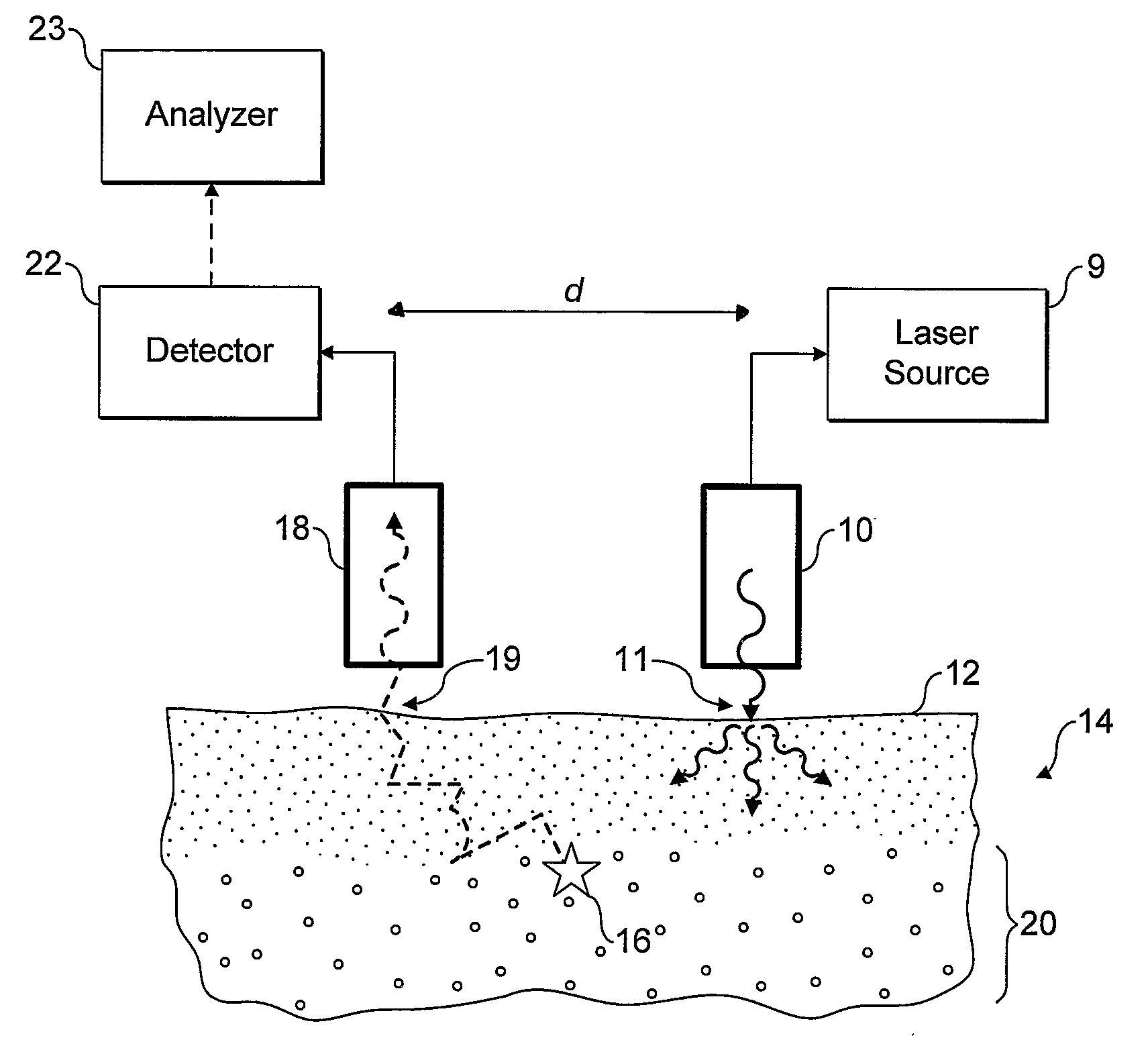
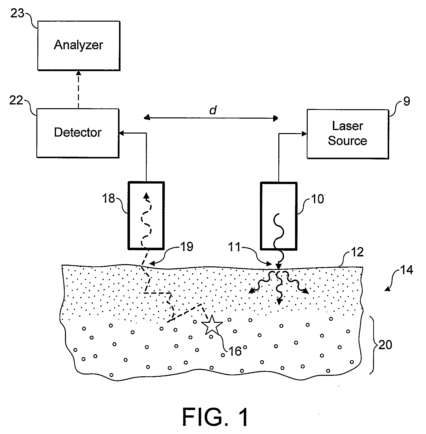
[0048]Referring now to FIG. 1 an embodiment of the invention is shown in operation, in schematic cross section. A light source 10, incorporating or supplied by laser 9, is used to irradiate a localised entry region 11 of a surface 12 of a sample 14. The incident radiation from the light source is scattered diffusely through the sample. Some of the radiation may be absorbed by the sample, some may give rise to optical emissions for example by fluorescence, and some re-emerges unchanged through the sample surface 12.

[0049]A small proportion of the photons of the incident radiation are inelastically scattered giving rise to Raman photons, for example as illustrated by Raman event 16. The Raman photons in turn are diffusively scattered through the sample. Some may be absorbed, for example giving rise to fluorescence, but some emerge unchanged through the surface 12 to be collected at collector 18. The likelihood of a Raman photon undergoing a second Raman event is very small.

[0050]The c...


PUM

PropertyMeasurementUnit
wavelengthaaaaaaaaaa
depthsaaaaaaaaaa

Abstract

Apparatus and methods for detecting Raman spectral features non destructively from sub-surface regions of a diffusely scattering sample are disclosed. Incident radiation is supplied at one or more sample surface entry regions, and light is collected from one or more collection regions spaced from the entry regions. Raman features are detected in the collected light, and depth information is derived according to the entry-collection spacings.

Description

FIELD OF THE INVENTION[0001]This invention relates to the field of Raman spectroscopy and, in particular, to apparatus for detecting Raman spectral features non-destructively from sub-surface regions within a macroscopic diffusely scattering sample.[0002]Diffusely scattering media are frequently encountered in many analytical applications. Examples of such analytical applications include but are not limited to monitoring of food products, colloids, polymers, catalysts, powders in general, coating technology and medical applications involving the probing of tissue and biochemical identification in medical studies and treatments. The samples encountered in such analytical applications are often highly heterogeneous and can be made of various layers each having a different chemical make-up. Therefore, a major goal for analytical science is to provide a method capable of determining the chemical composition of sub-surface layers in a non-destructive way.[0003]The benefits that can be de...

Claims


Application Information

Patent Timeline
Patent Type & Authority Applications(United States)
IPC IPC(8): G01J3/44A61B5/00A61B5/103G01N21/65
CPCA61B5/0059A61B5/0071A61B5/0075G01N2021/656A61B5/4504G01N21/65A61B5/441
Inventor MATOUSEK, PAVELPARKER, ANTHONY WILLIAM
Owner AGILENT TECH LDA UK LTD
Why Eureka
Try Eureka