Method of manufacturing laminated core

a manufacturing method and technology of laminated cores, applied in the direction of manufacturing stator/rotor bodies, magnetic circuit shapes/forms/construction, magnetic bodies, etc., can solve the problems of increasing cost, affecting the quality of laminated stator cores, etc., to achieve excellent shaping precision, reduce cost, and reduce the effect of bending processability

Inactive Publication Date: 2010-04-20
MITSUI HIGH TEC INC
View PDF19 Cites 37 Cited by
  • Summary
  • Abstract
  • Description
  • Claims
  • Application Information

AI Technical Summary

Benefits of technology

[0038]In the first aspect of the present invention, since the laminated yoke body constituting the yoke of the laminated stator core and the laminated magnetic body constituting a magnetic pole of the laminated stator core are independently formed, the band-shaped yoke core piece constituting the laminated yoke body has a band shape with a small width, and the concave connection portions are formed in the inner circumferential edge of the band-shaped yoke core piece, bending processability of the band-shaped yoke core piece is greatly enhanced to be satisfactory. Accordingly, it is possible to form the laminated yoke body, which is formed by winding the band-shaped yoke core piece, in a circular shape.
[0039]Since the laminated magnetic body is formed by laminating a predetermined number of magnetic core pieces in a caulking manner, the laminated magnetic body is manufactured without departure between the laminated magnetic core pieces. Accordingly, the laminated stator core in which a predetermined number of laminated magnetic bodies are coupled to the laminated yoke body has very excellent shaping precision.
[0040]In addition, since the laminated magnetic body is formed independently of the laminated yoke body, the winding work of winding a coil on the laminated magnetic body becomes very easy. Accordingly, it is possible to wind a coil with a high density and an excellent proportion.
[0041]As a result, according to the first aspect of the present invention, it is possible to manufacture a laminated stator core excellent in shaping precision and electrical characteristic.
[0042]In the second aspect of the present invention, since the laminated yoke body constituting the yoke of the laminated stator core and the laminated magnetic body constituting a magnetic pole of the laminated stator core are independently formed, the band-shaped yoke core piece constituting the laminated yoke body has a band shape with a small width, and the concave connection portions are formed in the inner circumferential edge of the band-shaped yoke core piece, bending processability of the band-shaped yoke core piece is greatly enhanced to be satisfactory. Accordingly, it is possible to form the laminated yoke body, which is formed by winding the band-shaped yoke core piece, in a circular shape.
[0043]By locally pressing the outer circumferential edge of the band-shaped yoke core piece to roll the band-shaped yoke core piece in a longitudinal direction before winding the band-shaped yoke core piece in a spiral shape, it is possible to easily wind the band-shaped yoke core piece. Accordingly, the degree of circularity of the laminated yoke body formed by winding the band-shaped yoke core piece is enhanced and thus the shaping precision of the laminated yoke body is enhanced.

Problems solved by technology

Since a large-sized manufacturing apparatus (molding apparatus) is required for manufacturing the large-sized laminated core such as a laminated stator core, the increase in cost is caused.
However, in the conventional manufacturing method described above, since the plane shape of the band-shaped core piece S constituting the laminated stator core A is very complex, it is difficult to wind the band-shaped core piece S in a circular shape due to deviation in deformation of each place at the time of winding it in a spiral shape or the like.
. . constituting the magnetic poles T, shaping precision of the manufactured laminated stator core A is severely deteriorated.
In this way, when the shaping precision of the laminated stator core A is deteriorated, there is a problem that an air gap from a rotor (not shown) has to be set great and it is possible to accomplish high power and high torque with increase in size due to deterioration in efficiency.
Accordingly, the coupling strength is decreased due to the gap generated between the laminated band-shaped core pieces S, thereby reducing the mechanical strength of the manufactured laminated stator core A.
In the conventional manufacturing method described above, since the plane shape of the band-shaped core piece S is very complex, the material yield of blanking the band-shaped core piece S is not good.
. . of the laminated stator core A are formed integrally with each other, it is difficult to perform the winding work of coils to the respective magnetic poles T, thereby causing deterioration in electrical characteristic due to disturbance of the coils.
. . manufactured through punching, laminating, and caulking processes by the use of a molding apparatus, the processes of manufacturing the laminated stator core B are very complex.
Accordingly, it cannot be told that the shaping precision of the manufactured laminated stator core B is satisfactory.
In the case that the above-mentioned method of manufacturing a laminated stator core is used for manufacturing a laminated stator core, since a laminated rotor core is generally smaller than the laminated stator core and it is very difficult to wind the band-shaped core pieces in a circular shape with a small curvature, the shaping precision of the manufactured laminated rotor core is deteriorated.
Accordingly, the processes of manufacturing the laminated rotor core as a complete product are complex, thereby causing deterioration in productivity.
In the above-mentioned method of manufacturing the laminated rotor core, since the respective rotor core pieces D are formed in a ring shape by winding them one by one, it is difficult to enhance the productivity of the laminated rotor core in which a predetermined number of rotor core pieces D.

Method used


Image

  • Method of manufacturing laminated core
  • Method of manufacturing laminated core
  • Method of manufacturing laminated core

Examples


first embodiment

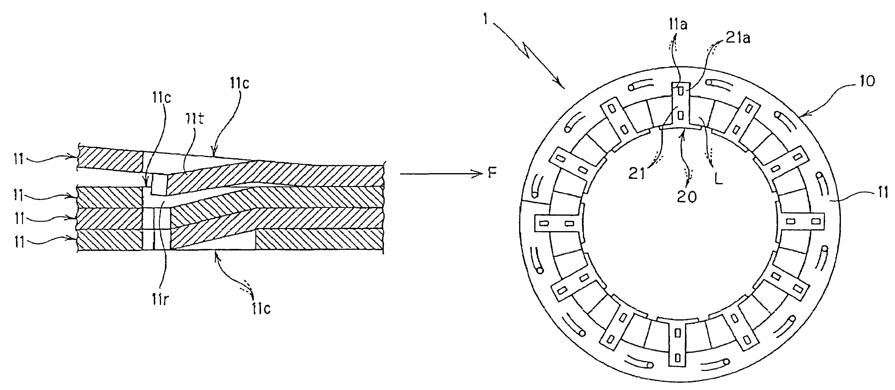
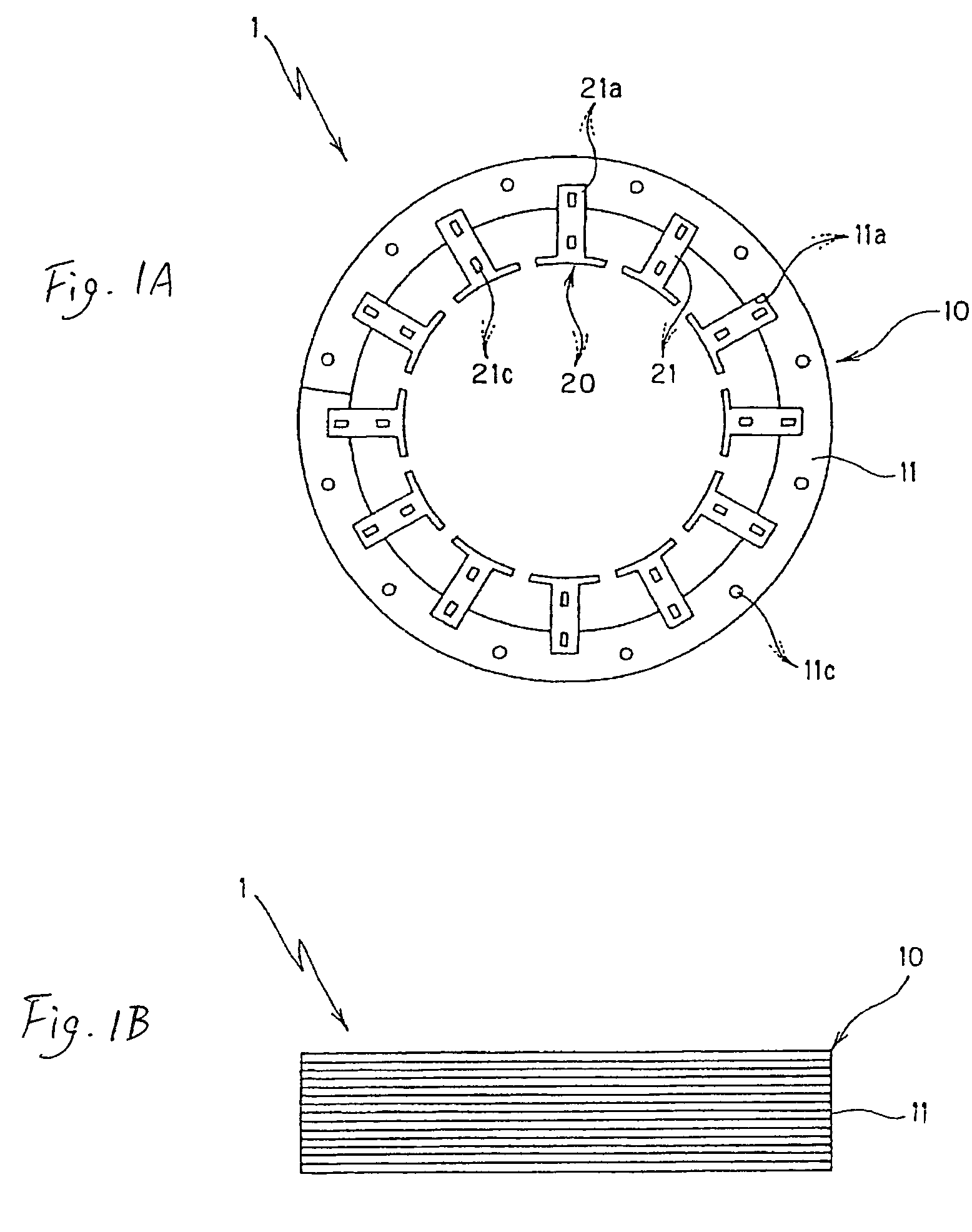
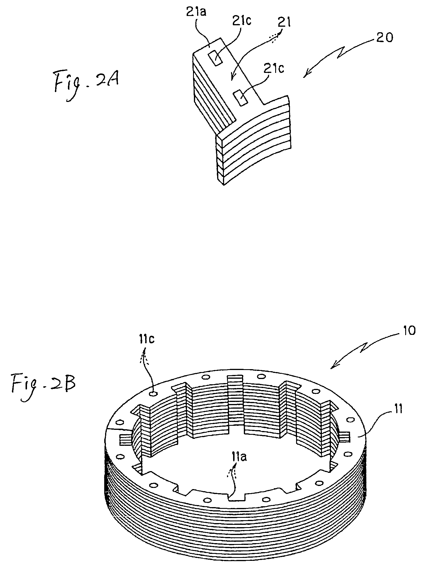
[0181]FIGS. 1 to 7 illustrate a method of manufacturing a laminated stator core according to the present invention. The laminated stator core 1 manufactured according to the present invention includes a laminated yoke body 10 having a band shape and a predetermined number of laminated magnetic bodies 20, 20, . . . (twelve in the first embodiment) coupled to the inner circumferential edge of the laminated yoke body 10.

[0182]As described later, the laminated yoke body 10 is constructed by winding and laminating a band-shaped yoke core piece 11, which is formed by punching a band-shaped steel plate (metal plate), in a spiral shape and coupling the laminated band-shaped steel plate in a caulking manner (caulking lamination). A predetermined number of concave connection portions 11a, 11a, . . . (twelve in the first embodiment) are formed in the inner circumferential edge of the laminated yoke body 10. Reference numeral 11c in the figures denotes a caulking portion formed in the band-shap...

second embodiment

[0213]FIGS. 10 and 11 show a method of manufacturing a laminated stator core according to a second embodiment of the present invention.

[0214]The method according to the second embodiment is basically similar to the method according to the first embodiment described with reference to FIGS. 1 to 9, except that the details of the processes of forming a laminated yoke body 10′ are different as described later. The laminated stator core manufactured according to the first embodiment is basically similar to the laminated stator core 1 shown in FIGS. 1 to 9, except that a partial shape of the laminated yoke body 10′ is different.

[0215]In the method of manufacturing a laminated stator core according to the second embodiment, first, as shown in FIG. 10A, a band-shaped yoke core piece 11′ is formed by punching an electromagnetic steel plate (metal plate) not shown.

[0216]The band-shaped yoke core piece 11′ has a shape that the yoke of the laminated stator core as a complete product is develope...

third embodiment

[0228]FIGS. 12 to 17 show a method of manufacturing a laminated stator core according to a third embodiment of the present invention. The laminated stator core 1 manufactured according to the third embodiment includes a laminated yoke body 10 having a ring shape and a predetermined number (twelve in the third embodiment) of laminated magnetic bodies 20, 20, . . . coupled to the inner circumference of the laminate yoke body 10.

[0229]The laminated yoke body 10 is constructed by winding and laminating the band-shaped yoke core piece 11, which is formed by punching a band-shaped steel plate (metal plate), in a spiral shape and coupling them in a caulking manner (caulking lamination) as described later. A predetermined number (twelve in the third embodiment) of concave connection portions 11a, 11a, . . . are formed in the inner circumferential edge of the laminated yoke body 10. Reference Numeral 11c in the figures denotes the caulking portions formed in the band-shaped yoke core piece 1...


PUM

PropertyMeasurementUnit
shapeaaaaaaaaaa
magneticaaaaaaaaaa
diameteraaaaaaaaaa

Abstract

A method of manufacturing a laminated stator core includes: forming a band-shaped yoke core piece having a shape that a yoke of the laminated stator core is developed in a straight line and having concave connection portions in the inner circumferential edge thereof by punching a metal plate; forming a laminated yoke body by winding and laminating the band-shaped yoke core piece in a spiral shape and coupling the laminated band-shaped yoke core piece in a caulking manner; forming a magnetic core piece having a convex connection portion at the base end thereof by punching a metal plate; forming a laminated magnetic body by laminating and coupling a predetermined number of the magnetic core pieces to each other in a caulking manner; and coupling the laminated yoke body and the laminated magnetic body to each other by winding a coil around the laminated magnetic body and then inserting the convex connection portions into the concave connection portions.

Description

TECHNICAL FIELD OF THE INVENTION[0001]The present invention relates to a method of manufacturing a laminated core, and more particularly, to a method of manufacturing a laminated core by winding and laminating band-shaped core pieces in a spiral shape and coupling the band-shaped core pieces to each other in a caulking manner.DESCRIPTION OF THE RELATED ART[0002]Large-sized ones are used as a laminated core built in a driving electric motor generating high power. Since a large-sized manufacturing apparatus (molding apparatus) is required for manufacturing the large-sized laminated core such as a laminated stator core, the increase in cost is caused. Further, since when a large-sized stator core piece is formed through punching, wide scraped portions are generated from the inside. Accordingly, a blanking yield of a core material is remarkably reduced.[0003]In order to solve the above-mentioned problem, there has been suggested a method of manufacturing a laminated stator core by formi...

Claims


Application Information

Patent Timeline
Patent Type & Authority Patents(United States)
IPC IPC(8): H02K15/02
CPCH02K1/148H02K1/2766H02K15/022H02K15/026H02K15/03Y10T29/49078Y10T29/49071Y10T29/49009Y10T29/49012Y10T29/53143H02K2201/09
Inventor MITSUI, YOSHIAKIFUJITA, KATSUFUSA
Owner MITSUI HIGH TEC INC
Why Eureka
Try Eureka