Sling release mechanism

a release mechanism and sling technology, applied in emergency apparatus, parachutes, transportation and packaging, etc., can solve the problems of pyrotechnic cord cutters above moderate size that are too large and powerful for safe handling by personnel, and the parachute system to fail, so as to reduce the necessary size of the retainer

Active Publication Date: 2010-04-20
FOX JR ROY L
View PDF18 Cites 3 Cited by
  • Summary
  • Abstract
  • Description
  • Claims
  • Application Information

AI Technical Summary

Benefits of technology

[0015]In this configuration, the leverage provided by the two hinge plates allows the retainer to exercise a significantly augmented force to hold the shaped end section of the pivot arm in place within the receiver of the inner latch plate. This significantly reduces the necessary size of the retainer and the means to release the retainer from the outer hinge plate. In one embodiment, the retainer is a cut loop and the release means is a cord cutter. Because the cut loop in this invention needs only to be sufficiently strong to resist the torque on the outer hinge plate imparted by the pivot arm, which is only a small fraction of the weight of the platform, and not the entire weight of the payload platform, a much smaller cord, and thus a much smaller cord cutter may be used than in conventional release means.

Problems solved by technology

At times, people in isolated areas, such as jungles, deserts, mountains, polar regions, or combat zones, are in need of essential supplies, including food and medical supplies, but are not within access to an airport at which a supply plane could land.
Use of a series of parachute deployments is often necessary because the force and impulse on the suspension lines and straps of a main parachute (i.e., one large enough to slow the cargo platform to an acceptable landing velocity) deploying at the terminal, free-fall velocity of the cargo platform would be excessive, causing the parachute system to fail.
A pyrotechnic cord cutter for payloads above a moderate size becomes too large for practical handling and would incorporate an explosive charge too large and powerful for safe handling by personnel.

Method used


Image

  • Sling release mechanism
  • Sling release mechanism
  • Sling release mechanism

Examples


Embodiment Construction

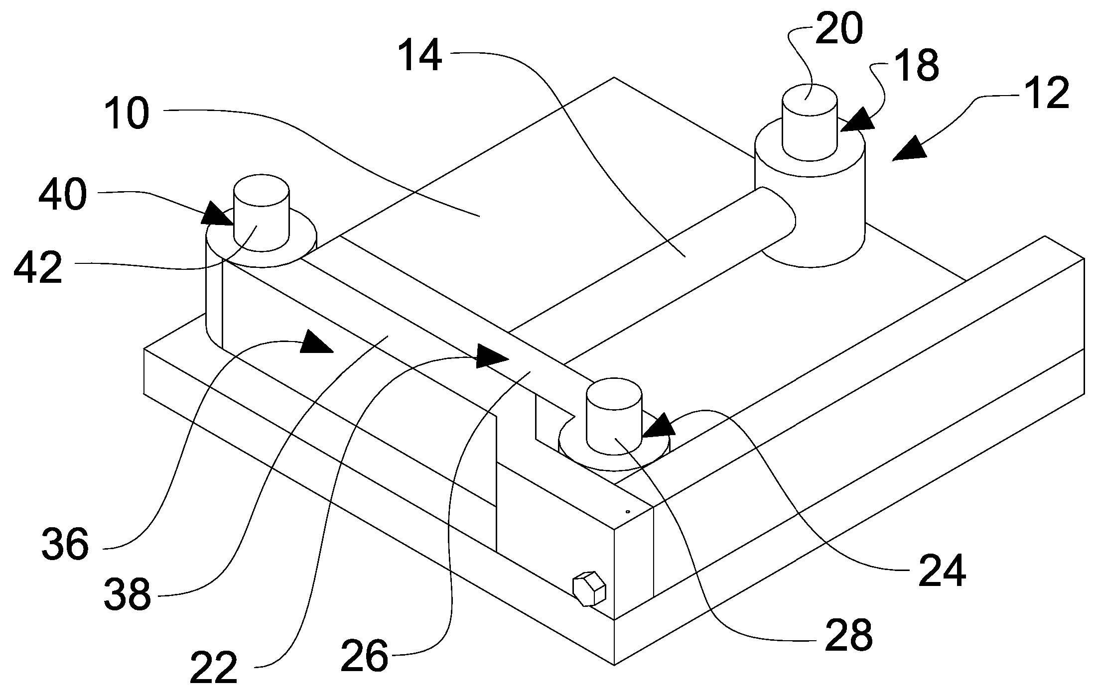
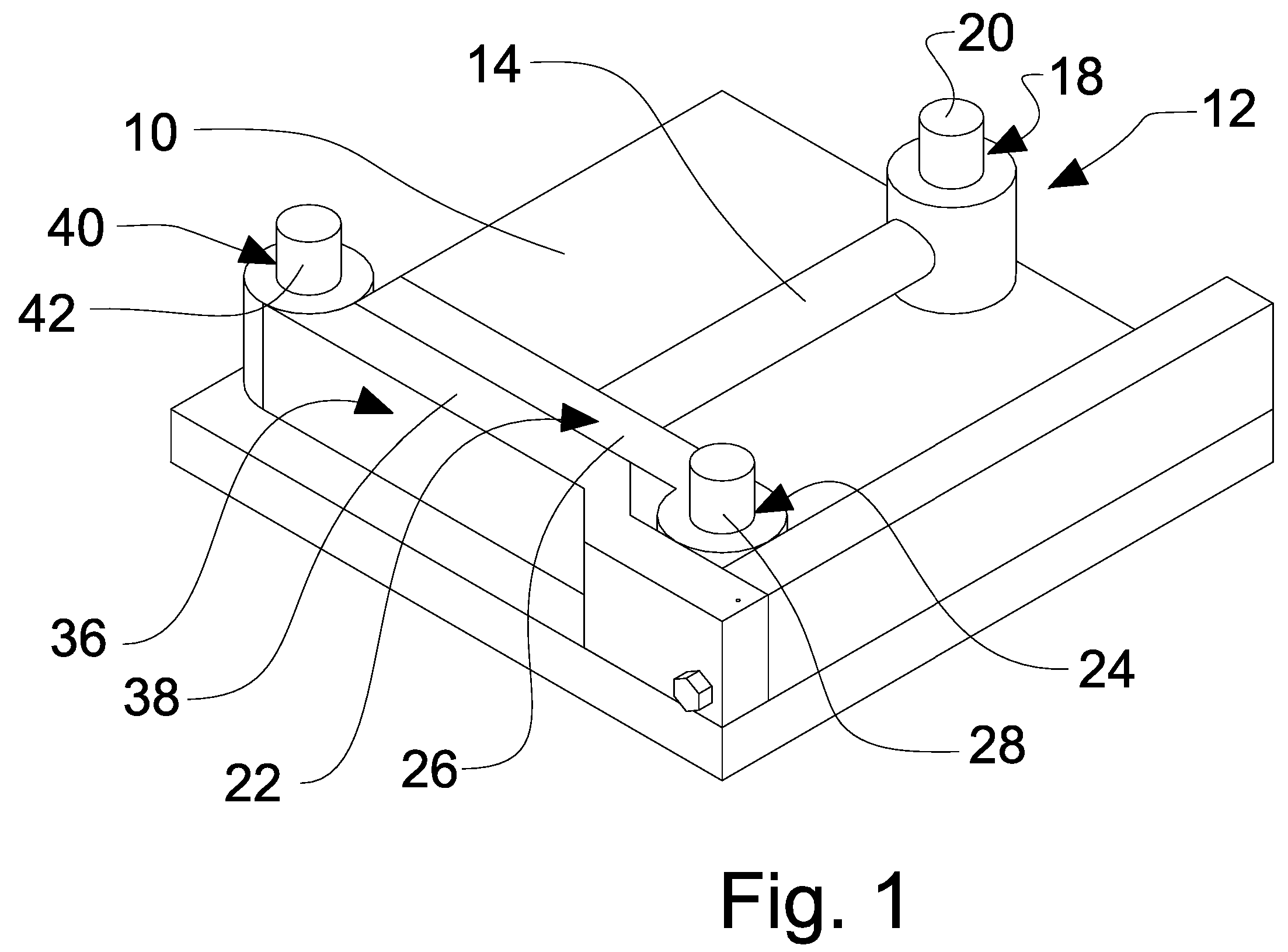
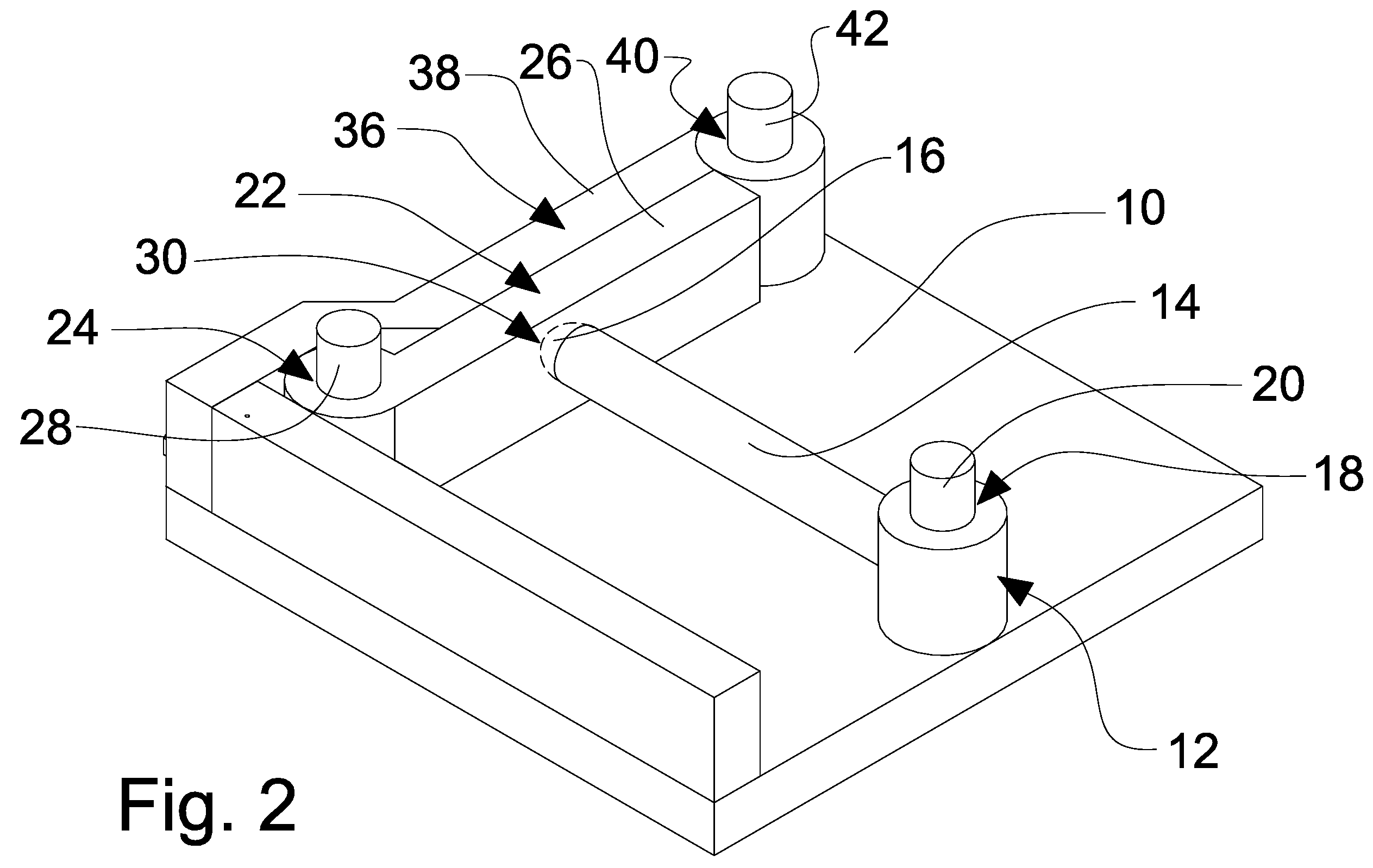
[0024]As shown in FIGS. 1 and 2, a preferred embodiment of a sling release mechanism is comprised, first, of a body 10, which serves as the base or foundation upon which all other components are assembled. The base can be fabricated of any commonly known, structurally strong material, such as metal, including but not limited to steel, stainless steel, cast iron, aluminum, aluminum alloys, titanium or titanium alloys.

[0025]Attached to the body is a pivot arm 12. The pivot arm 12 has an elongated section 14. At one end of the elongated section 14 is a shaped end section 16 and at the other, a means for articulating with the body 10. This means for articulating with the body 10 comprises, preferably, an aperture 18. A first pin 20 or the like passes through the aperture 18 with minimal clearance and conjoins at one or both of its ends with the body10. The pivot arm 12 can then freely articulate around the first pin 20. The shaped end section 16 is disposed at the opposite end of the el...


PUM


Abstract

A sling release mechanism for releasing the sling of a drogue parachute from a descending aerially delivered cargo pallet. The sling release mechanism has a body, with which a pivot arm, an inner and an outer hinge plate articulate. The inner and outer hinge plates articulate in opposite directions when in use. The inner hinge plate has a cavity or receiver into which the end tip of the pivot arm may engage. The end of a parachute sling is placed over the pivot arm, and the pivot arm and inner hinge plate are articulated to engage the pivot pin end with the receiver of the inner hinge plate. The outer hinge plate is then articulated to engage the inner hinge plate, and is held in place with a releasable retainer. The parachute sling is released by releasing the retainer, allowing the outer and then the inner hinge plates to articulate, thereby releasing the pivot arm to articulate, after which the end of the parachute sling slides off the pivot pin. Other embodiments include multiple mechanisms for releasing a plurality of slings.

Description

PRIOR APPLICATIONS[0001]Applicant claims the benefit of the filing data of Provisional Application, Ser. No. 60 / 790,653, entitled Sling Release Mechanism and filed Apr. 10, 2006BACKGROUND OF THE INVENTION[0002]1. Field of the Invention[0003]The present invention relates to release mechanisms for releasing a deployed parachute from a suspended load in a controlled manner.[0004]2. Description of the Prior Art[0005]Aerial delivery is a means frequently used for transporting cargo quickly to areas of limited or hostile access, without the availability of any nearby airports. At times, people in isolated areas, such as jungles, deserts, mountains, polar regions, or combat zones, are in need of essential supplies, including food and medical supplies, but are not within access to an airport at which a supply plane could land. In these instances, aerial delivery of cargo from in-flight aircraft is the sole option. These aerial delivery systems involve the use of parachute systems to slow th...

Claims


Application Information

Patent Timeline
Patent Type & Authority Patents(United States)
IPC IPC(8): B64D17/38
CPCB64D17/38
Inventor FOX, JR., ROY L
Owner FOX JR ROY L
Why Eureka
Try Eureka