Chain transmission device

a transmission device and chain technology, applied in the direction of gearing, gearing elements, hoisting equipments, etc., can solve the problems of inability to adequately reduce the noise of timing transmission, the elastic member is found to be incapable of reducing these noises and vibrations, and achieves the effect of reducing the overall impact force applied to the elastic member, improving the endurance of the elastic member, and reducing the overall impact for

Inactive Publication Date: 2010-04-20
TSUBAKIMOTO CHAIN CO
View PDF6 Cites 28 Cited by
  • Summary
  • Abstract
  • Description
  • Claims
  • Application Information

AI Technical Summary

Benefits of technology

[0012]Because the sprocket has a plurality of different tooth form pitch angles, and the tooth form pitch angles are arranged irregularly along the circumferential direction of the sprocket's pitch circle, the engagement impact between a roller or bushing and the tooth gap bottom of the sprocket is reduced, and the elastic member becomes more effective in vibration reduction. Furthermore, since the overall impact force applied to the elastic member is reduced, the endurance of the elastic member is improved.
[0013]The timing of engagement of a roller or bushing with the sprocket is also shifted. Consequently, vibrations and noises having an order determined by the number of sprocket teeth, which could not be effectively reduced by the elastic member alone, are reduced. Thus, the overall sounds produced by the chain transmission are significantly reduced by the combined effect of the shift in engagement timing and the vibration-reduction of the elastic member.

Problems solved by technology

The principal source of timing transmission noise is the engagement sound generated as the chain engages the sprockets.
The elastic member has been found to be incapable of reducing these noises and vibrations adequately.

Method used


Image

  • Chain transmission device
  • Chain transmission device
  • Chain transmission device

Examples


first embodiment

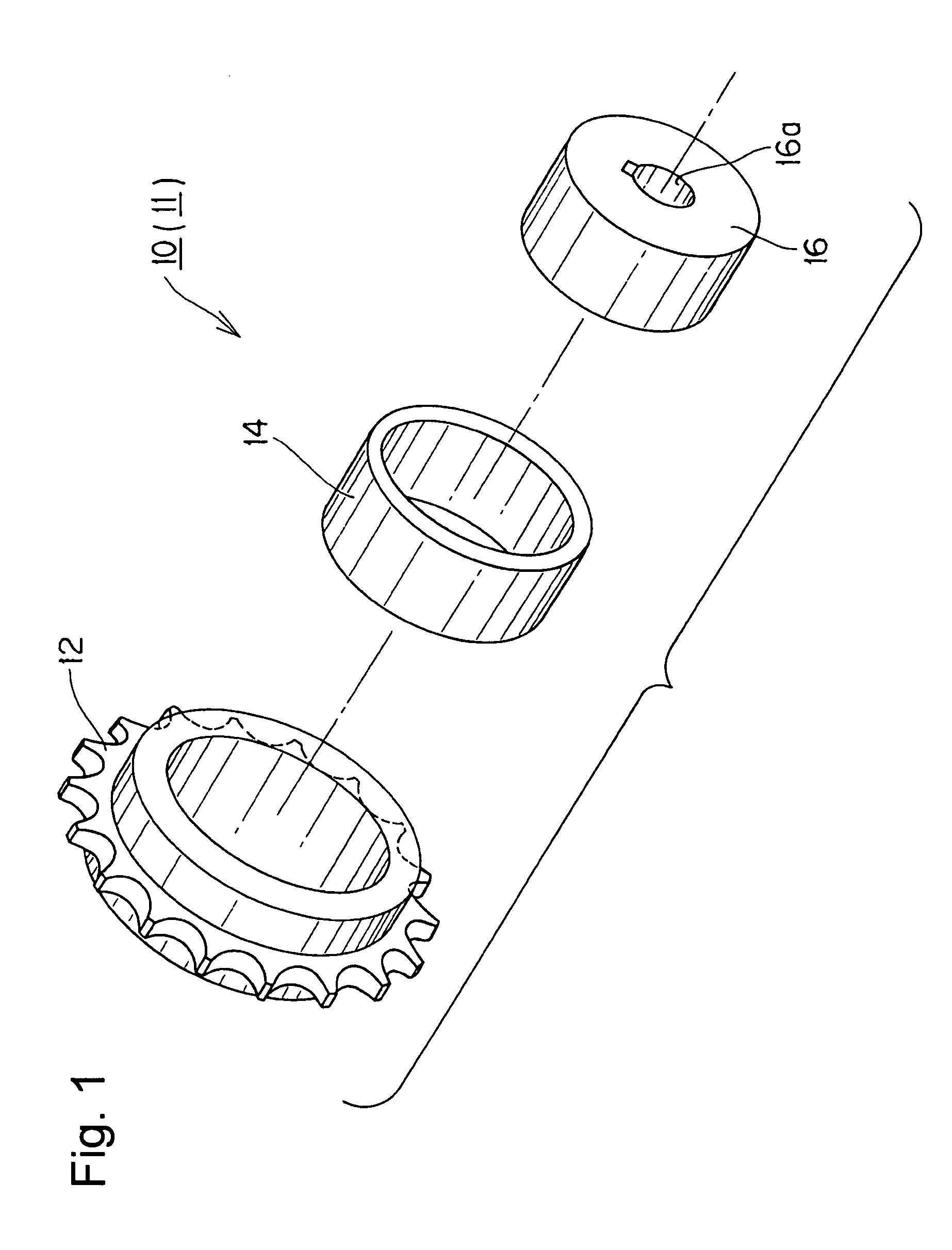
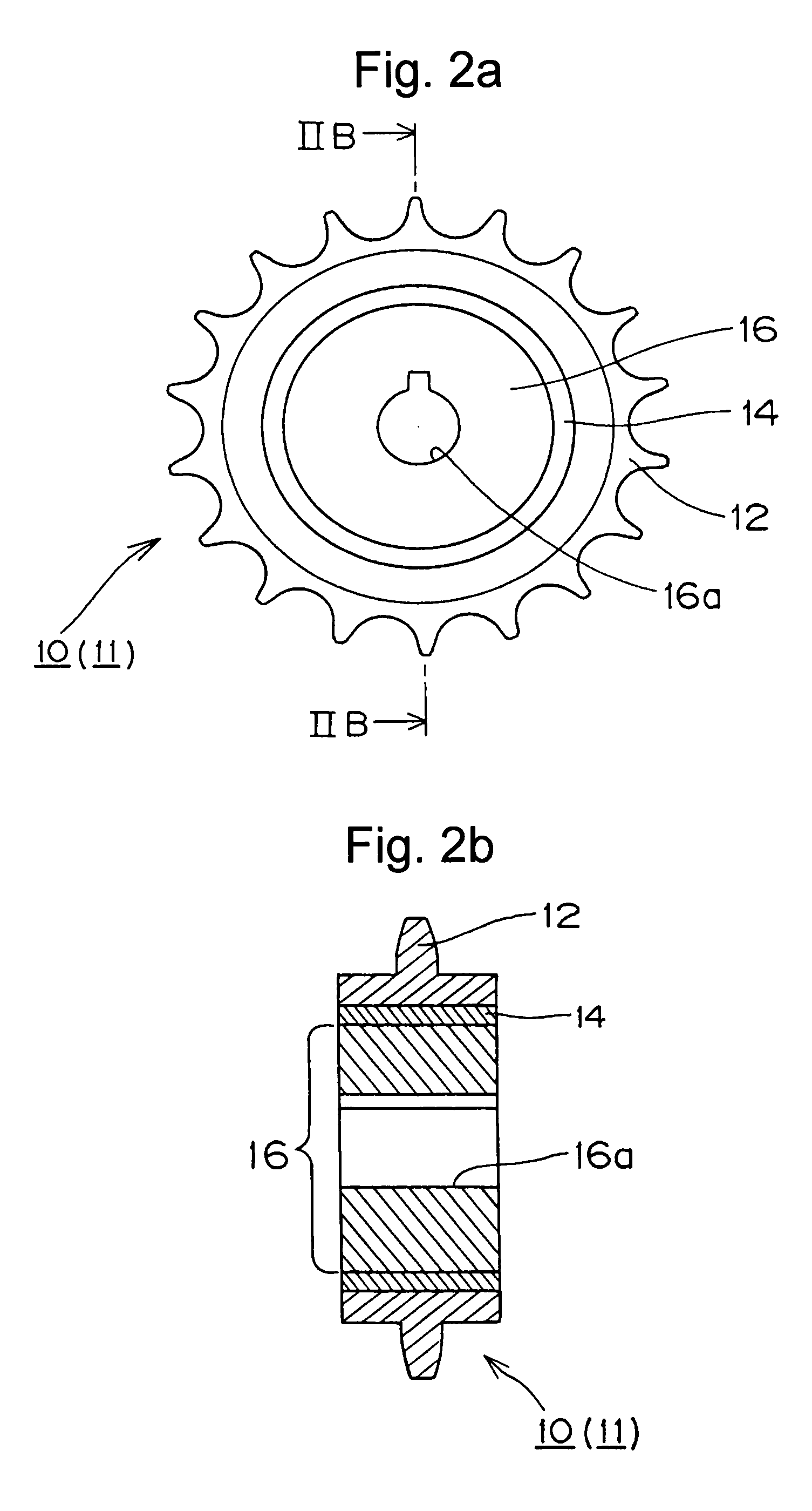
[0028]As shown in FIGS. 1, 2(a) and 2(b), in the invention, an elastic member 14 is attached to an inner hub 16 of the sprocket. The hub includes a keyed shaft-receiving hole 16a, to which a shaft (not shown) can be fitted. An outer circumferential member 12, on which the sprocket teeth are formed, surrounds the elastic member 14. The elastic material can be resin, rubber, metal or the like, but the material of the elastic member should have a Young modulus smaller than that of the outer circumferential member 12.

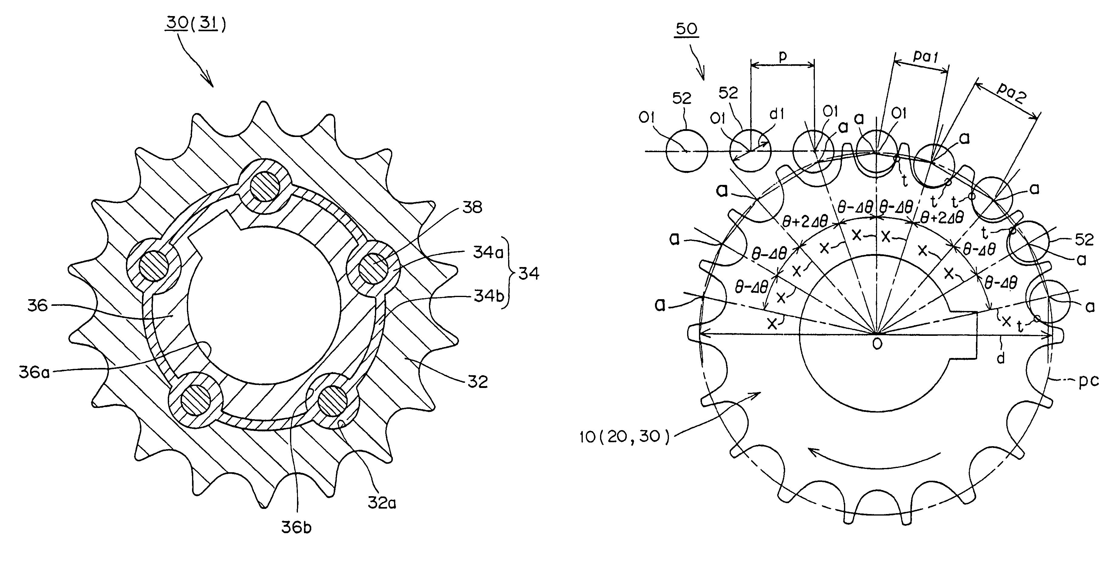
[0029]The sprocket 10 can have two different tooth form pitch angles, θ−Δθ and θ+2Δθ. The tooth form pitch angle θ−Δθ is smaller than a standard pitch angle θ by an angle Δθ, and a tooth form pitch angle θ+2Δθ is larger than the standard pitch angle θ by two times the angle Δθ. In order to allow engagement of the chain rollers with the sprocket teeth, Δθ must not be greater than ¼ the standard pitch angle θ (that is, Δθ≦θ / 4). Specifically, if the sprocket 10 has eighteen te...

second embodiment

[0034]A chain transmission according to the invention will now be described with reference to FIGS. 3, 4(a), 4(b), and 8. As apparent from FIGS. 3, 4(a) and 4(b), an elastic member 24 is attached to an outer circumferential member 22, on which teeth 22a are formed for engagement with the rollers or bushings of a chain. The elastic member 24 is composed of a material having a Young's modulus smaller than that of the outer circumferential member 22.

[0035]As in the case of the sprocket 10 of FIGS. 1, 2(a) and 2(b), the sprocket 20 has two different tooth form pitch angles θ−Δθ and θ+2Δθ, as shown in FIG. 8. Since the tooth form pitch angles are arranged irregularly along the circumferential direction of the sprocket's pitch circle, the sprocket's vibration-reducing performance and the endurance of the elastic member are improved, and, at the same time, vibration and noise having an order determined by the number of sprocket teeth, are reduced even though they could not be effectively r...

third embodiment

[0036]In the sprocket of a chain transmission according to the invention, as shown in FIGS. 5 and 6, an elastic member 34 is sandwiched between an inner circumferential hub 36 and an outer circumferential member 32 on which sprocket teeth are formed. The hub has a keyed shaft hole 36a to which a shaft can be fitted. The elastic member 34 is composed of a material such as resin, rubber, metal, or the like, having a Young's modulus lower than that of the outer circumferential member 32.

[0037]The elastic member 34 is formed with a plurality of spaced cylindrical portions 34a, disposed at equal intervals around the circumference of the elastic member. The cylindrical members are connected by arc-shaped plates 34b. The elastic member 34 is sandwiched between the outer circumferential surface of the hub 36, and an inner circumferential surface of the toothed outer circumferential member 32. The cylindrical portions 34a are fitted between opposed concave grooves 36b and 32a, respectively d...


PUM


Abstract

In a chain transmission, vibration reduction is improved by an elastic member, sandwiched between an inner hub of a sprocket and a toothed outer circumferential member, in combination with a sprocket tooth configuration in which two or three different tooth form pitch angles are arranged irregularly along the sprocket's pitch circle.

Description

CROSS-REFERENCE TO RELATED APPLICATION[0001]This application claims priority on the basis of Japanese application 2007-008391, filed Jan. 17, 2007. The disclosure of Japanese application 2007-008391 is hereby incorporated by reference.FIELD OF THE INVENTION[0002]This invention relates to improvements in chain transmissions for reducing vibration and noise generated when the rollers of a standard roller chain or the bushings of a standard rollerless bushing chain engage with sprocket teeth, and for effecting smooth disengagement of the rollers or bushings from the sprocket teeth.BACKGROUND OF THE INVENTION[0003]Chain transmissions, in which a chain is engaged with a driving sprocket and one or more driven sprockets, have been widely used as timing transmissions in automobile engines for driving valve-operating cam or cams from the engine crankshaft.[0004]Recent demand for higher power automobile engines, coupled with public consciousness of environmental problems, has led to the deve...

Claims


Application Information

Patent Timeline
Patent Type & Authority Patents(United States)
IPC IPC(8): F16H7/06
CPCF16H55/30F16H2055/306
Inventor SAKURA, SHUNJIHIRAI, AKIRA
Owner TSUBAKIMOTO CHAIN CO
Why Eureka
Try Eureka