Integrated power device having a start-up structure

a power device and integrated technology, applied in the direction of electrical equipment, instruments, static storage, etc., can solve the problems of high production cost, high integration cost, and substantial problems in the fabrication of ic control devices

Active Publication Date: 2010-04-20
STMICROELECTRONICS SRL
View PDF20 Cites 8 Cited by
  • Summary
  • Abstract
  • Description
  • Claims
  • Application Information

AI Technical Summary

Problems solved by technology

However, in the majority of cases, this entails substantial problems in the fabrication of the IC control device.
For example, integration of the IC device, which must be a high-voltage one, entails high production costs, in so far as it must be obtained on a high-voltage epitaxial thickness capable of supporting the inhibition voltage required and enable introduction of the necessary edge structure.
In addition, the fabrication of the IC control device on a high-voltage epitaxial thickness causes problems linked to the production of the IC device.
In fact, when this is inhibited, if a voltage is applied from the outside which is higher than the breakdown voltage of the IC device, a process of avalanche multiplication is triggered therein and produces a current (avalanche current) that can destroy the IC device.
When this does not occur, there is destruction of the entire SMART-Power device.

Method used


Image

  • Integrated power device having a start-up structure
  • Integrated power device having a start-up structure
  • Integrated power device having a start-up structure

Examples


Embodiment Construction

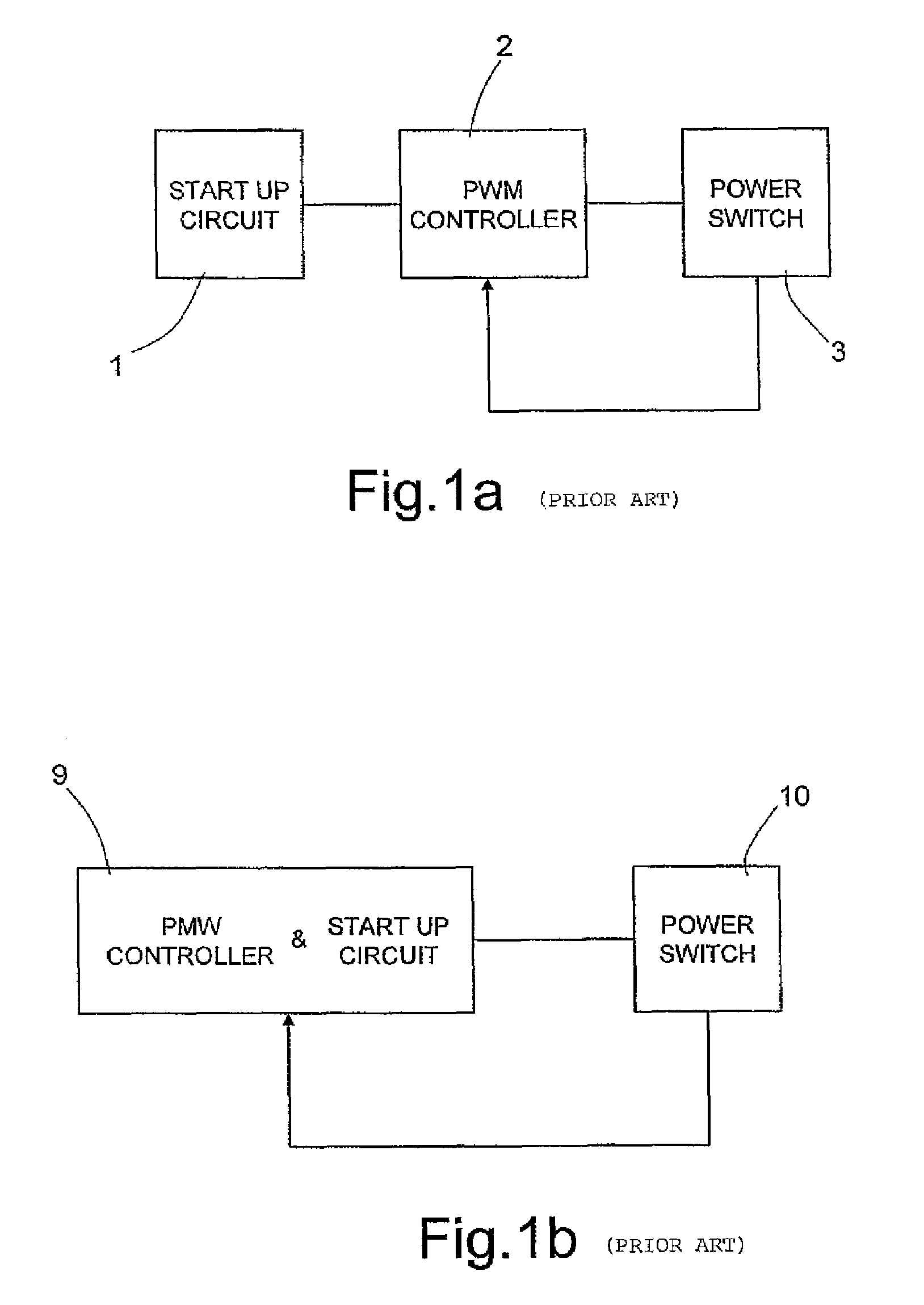
[0018]FIG. 1a shows the block diagram of an SMPS application comprising a start-up circuit 1 connected to a PWM (Pulse Width Modulation) controller 2, which is in turn connected to a power device 3 that functions as switch. The power device 3 is moreover feedback-connected to the PWM controller 2. In the SMPS application, the start-up block 1 turns on, or turns back on, the PWM controller 2, which in turn controls the state of the power device 3.

[0019]FIG. 1b shows a different known scheme in which the start-up circuit and the PWM controller are integrated in a single control block 9, which controls a power stage 10 integrating a power device 18.

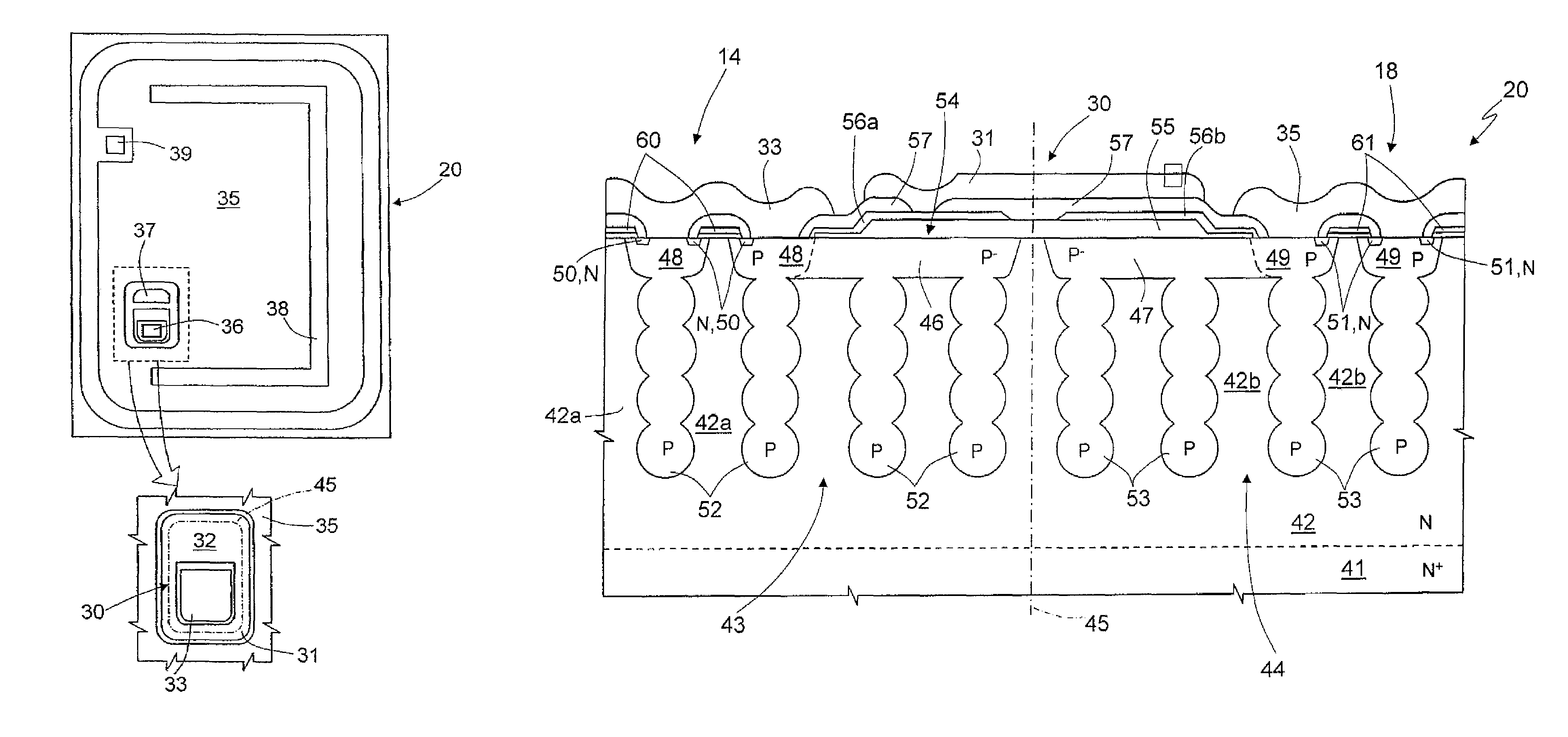
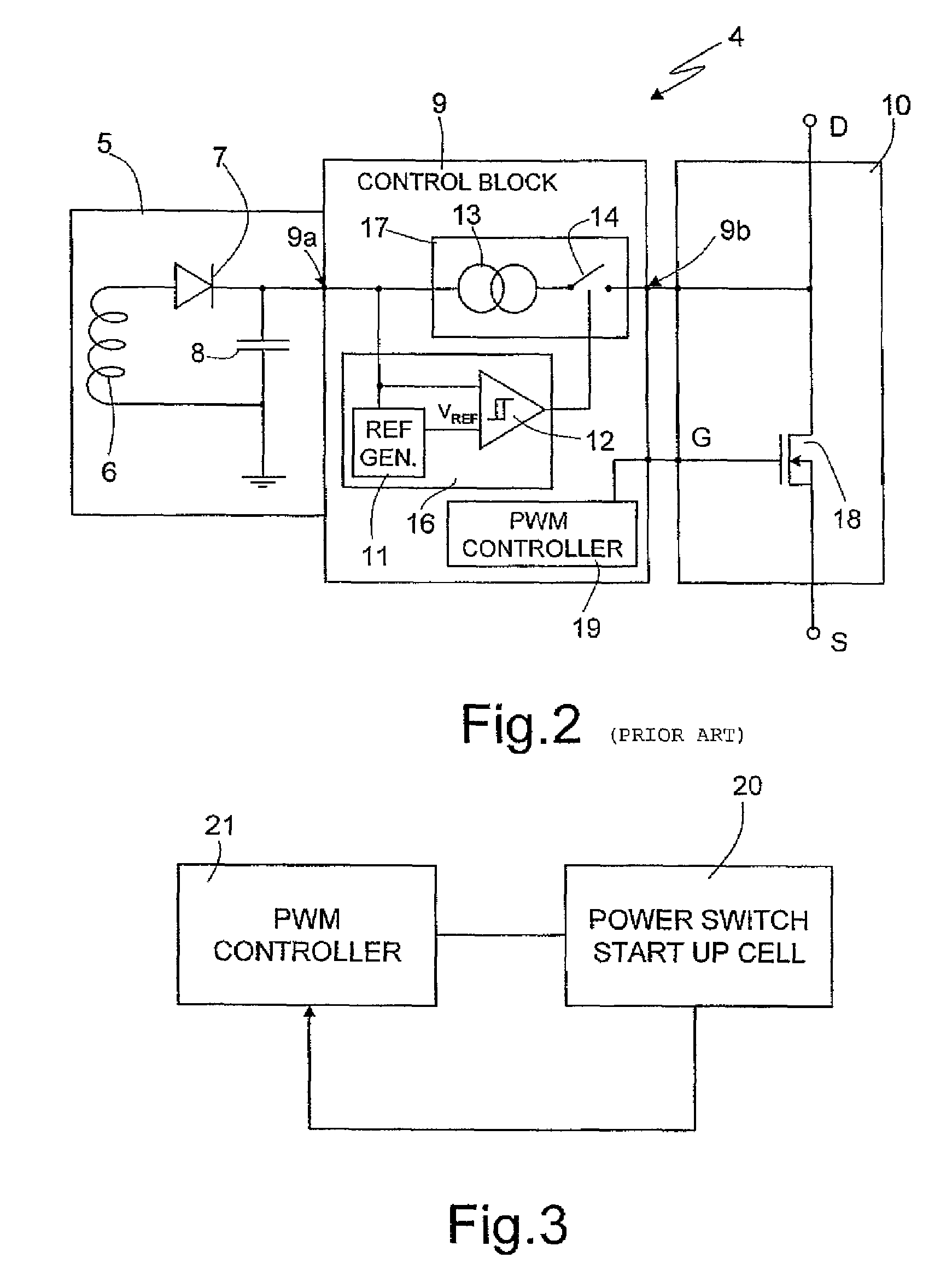
[0020]FIG. 2 shows a circuit diagram implementing the known scheme of FIG. 1b as regards the components necessary for understanding the invention. In detail, the control block 9 comprises a start-up control circuit 16, a start-up circuit 17 and a PWM controller 19, of a known type and thus not shown in detail. The start-up control circuit 16...


PUM


Abstract

An integrated power device includes a semiconductor body of a first conductivity type comprising a first region accommodating a start-up structure, and a second region accommodating a power structure. The two structures are separated from one another by an edge structure and are arranged in a mirror configuration with respect to a symmetry line of the edge structure. Both the start-up structure and the power structure are obtained using MOSFET devices. Both MOSFET devices are multi-drain MOSFET devices, having mesh regions, source regions and gate regions separated from one another. In addition, both MOSFET devices have drain regions delimited by columns that repeat periodically at a fixed distance. Between the two MOSFET devices there is an electrical insulation of at least 25 V.

Description

BACKGROUND OF THE INVENTION[0001]1. Field of the Invention[0002]The present invention relates to an integrated power device having a start-up structure. More specifically the invention relates to the integration of a start-up structure in a power device.[0003]2. Discussion of the Related Art[0004]The invention relates, in particular, but not exclusively, to a multi-drain (MDmesh) MOSFET power device, and the ensuing description is made with reference to this field but only for the purpose of simplifying the explanation.[0005]In the course of the last few years, particular interest has been directed to semiconductor power devices for switched-mode power-supply (SMPS) applications, which include control circuits. Power devices in which control functions are integrated, which enable, for example, self-protection of the power device in all operating conditions, are referred to as SMART-Power devices. For these devices, studies have been conducted on the integration also of the start-up ...

Claims


Application Information

Patent Timeline
Patent Type & Authority Patents(United States)
IPC IPC(8): H01L29/00
CPCH01L21/823487H01L27/088H01L29/7811H01L29/7803H01L29/0634H01L29/1095
Inventor SAGGIO, MARIO GIUSEPPEMINNOLO, ANTONINO LONGOGERMANA', ROSALIA
Owner STMICROELECTRONICS SRL
Why Eureka
Try Eureka